Self-help feeder for poultry

A technology for feeders and poultry, applied in applications, poultry industry, animal repellent, etc., can solve the problems of increasing manual workload, bringing germs to chickens, increasing feeding costs, etc., to reduce feeding costs, The effect of simple structure and ingenious design

Active Publication Date: 2017-10-13
盐城珞琦斯特家居用品有限公司
2 Cites 6 Cited by

AI-Extracted Technical Summary

Problems solved by technology

At present, the feeders on the market do not have the ability to prevent rodents, snakes, insects and other non-artificial breeding organisms from stealing feed, which wastes a lot of feed and increase...

Method used

The present invention adopts such structural settings, by being provided with anti-rat door 7 on feeding trough 8, anti-rat door 7 is driven by self-service anti-rat door closing mechanism, thereby realizing the closing of feeding trough 8 , Effectively prevent rodents, snakes, insects and other non-artificial breeding organisms from stealing feed, eliminate the great waste ...

Abstract

The invention relates to the technical field of poultry feeder, in particular to a self-help feeder for poultry. The feeder comprises a feed bucket, feeding troughs are arranged on the two sides of the feed bucket bottom, the feeding troughs and the feed bucket are arranged in a communicated mode, a mouse door is arranged correspondingly above each feeding trough, and the closing of the feeding troughs is achieved through a self-help mouse control door closing mechanism. Such a structure arrangement is adopted by the self-help feeder for poultry, the closing of the feeding trough is achieved through the arrangement of the mouse doors above the feeding troughs and the working of the mouse doors driven by the self-help mouse door closing mechanism; the self-help feeder for poultry is simple in structure and ingenious in design, can achieve the completion of a feeding process through the self-help of poultries, at the same time has the advantages of preventing food theft by other non-human feeding animals of mice, snakes, insects and the like, avoiding the huge waste of feed, reducing the cost of feeding, and having strong applicability.

Application Domain

Technology Topic

Image

  • Self-help feeder for poultry
  • Self-help feeder for poultry
  • Self-help feeder for poultry

Examples

  • Experimental program(1)

Example Embodiment

[0022] The technical solution of the present invention will be described below with reference to the drawings and embodiments.
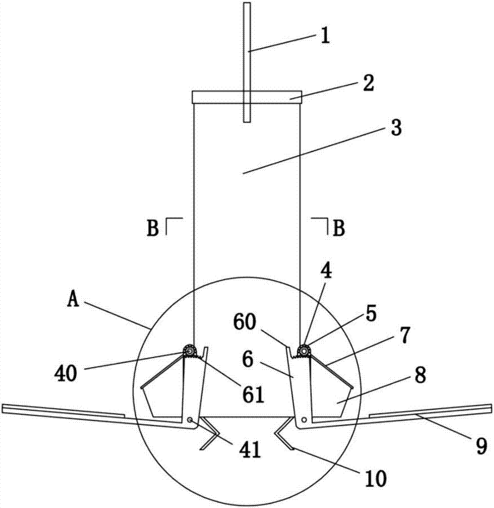
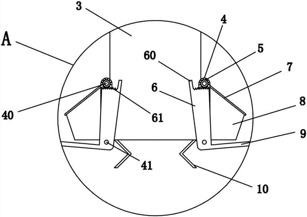
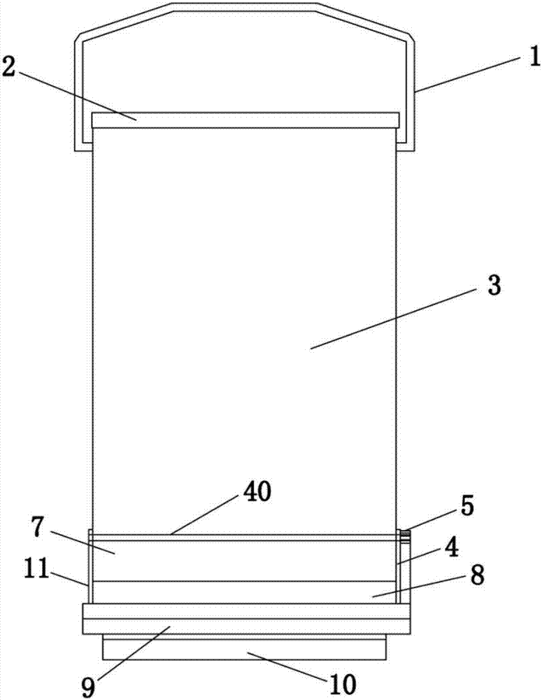
[0023] Such as Figure 1 to Figure 5 As shown, the self-service feeder for poultry according to the present invention includes a feed bucket 3, and two sides of the bottom of the feed bucket 3 are provided with feeding troughs 8 respectively. The feed trough 8 is connected with the feed bucket 3, and the feed trough 8 Correspondingly, a rat-proof door 7 is provided, and the rat-proof door 7 closes the feeding trough 8 through a self-service rat-proof door closing mechanism. The above constitutes the basic structure of the present invention.
[0024] The present invention adopts such a structural arrangement. By providing a rat-proof door 7 on the feeding trough 8, the rat-proof door 7 is driven by a self-service rat-proof door closing mechanism, thereby closing the feeding trough 8 and effectively To prevent the stealing of feed by various non-artificial feeding organisms such as rodents, snakes, insects, etc., it can prevent large waste of feed and reduce feeding costs. Its structure is simple, its design is ingenious, and its applicability is strong.
[0025] More specifically, the self-service rat-proof door closing mechanism includes bearing seat plate one 4, gear 5, toggle plate 6, foot pedal 9, bearing seat plate two 11, rotating shaft one 40 and rotating shaft two 41, bearing seat plate No. 4 and bearing seat plate No. 11 are respectively arranged on both sides of the feeding trough 8. The rotating shaft No. 40 is arranged at the upper end position between the bearing seat plate No. 4 and the bearing seat plate No. 11 and above the feeding trough 8. Position, the rat-proof door 7 is fixed on the first shaft 40, the gear 5 is fixed on the end position of the first shaft 40, and the second shaft 41 is provided at the lower end position between the bearing seat plate one 4 and the bearing seat plate two 11. The pedal 9 is hinged on the second shaft 41 and is located below the feeding trough 8. The toggle plate 6 is vertically connected to the side of the pedal 9 and the toggle plate 6 is arranged at the end of the second shaft 41 , The toggle plate 6 is provided with a number of clamping teeth 61 meshing with the gear 5. This structure is adopted to realize the poultry self-feeding process. Its working principle is: when poultry wants to eat, they only need to step on the foot pedal 9. Since the toggle plate 6 is vertically connected to the foot pedal 9, the poultry uses its own The weight realizes the lever principle through the second shaft 41, and realizes the effect that the tooth 61 on the toggle plate 6 drives the gear 5 to rotate. The gear 5 drives the shaft 40 to rotate clockwise, and the shaft 40 drives the rat-proof door 7 to rotate clockwise. The opening of the feeding trough 8 can be opened so that the poultry can eat the feed in the feeding trough 8; when the poultry is full, leave the foot pedal 9 and the foot pedal 9 loses the weight of the poultry. At this time, the rat-proof door 7 Due to its own weight, it turns counterclockwise and drives the shaft 40 to rotate counterclockwise, and the shaft 40 drives the gear 5 to rotate until the rat-proof door 7 resets and covers the opening of the feeding trough 8.
[0026] More specifically, the toggle plate 6 is further provided with a brake limit block 60, and the brake limit block 60 is provided at the side of the last latching tooth 61 of the plurality of latching teeth 61. By adopting such a structural arrangement, the stopper 60 effectively prevents the clamping tooth 61 from coming out of the meshing arrangement with the gear, and at the same time, it also acts to limit the opening degree of the rat-proof door 7 by braking the gear 5.
[0027] More specifically, the weight of the rat-proof door 7 and the foot pedal 9 are equal. With such a structural arrangement, it is realized that when a bird steps on the pedal 9, the weight of the pedal 9 exceeds the rat-proof door 7, and the effect of the pedal 9 driving the rat-proof door 7 is realized. When the bird leaves the pedal 9 At this time, due to the action of gravity, the anti-rat door 7 realizes the effect that the anti-rat door 7 drives the foot pedal 9 and resets again.
[0028] More specifically, the rat-proof door 7 is larger than the opening of the feeding trough 8. By adopting such a structure, the rat-proof door 7 can completely cover the opening of the feeding trough 8, which can effectively prevent rain and prevent the feed from being damp. At the same time, it can protect the rat-proof door 7 through the feeding trough 8. Limit.
[0029] More specifically, the bottom of the feed bucket 3 is provided with a supporting foot 10 that can support a feeder. By adopting such a structure, the supporting foot 10 effectively has the effect of suspending the footrest 9; in addition, the supporting foot 10 can also be used to facilitate the placement of the feeder in wasteland, woodland, grassland, orchard, and farmland. , Corn fields, sorghum and other places.
[0030] More specifically, the top of the feed bucket 3 is provided with a feed bucket cover 2 correspondingly, and the feed bucket cover 2 is provided with a handle 1. With such a structure, the handle 1 facilitates the operation of the lid 2 of the feed bucket.
[0031] More specifically, the feed bucket 3 is arranged in a rectangular parallelepiped structure.
[0032] The working process of the present invention: first open the feed bucket lid 2 through the handle 1, and then feed according to the size of the feed bucket 3 (it can also be connected to the feed bucket 3 through an automatic conveying system for quantitative conveying and feeding), because the feeding trough 8 is set in The bottom position of the feed bucket 3 is connected with the feed bucket 3, so the added feed can flow into the feeding trough 8 (the present invention can also set a baffle plate at the connection between the feeding trough 8 and the feeding bucket 3 to achieve The feed that flows into the feeding trough 8 is limited to the height). When the poultry wants to eat, they only need to step on the foot pedal 9. Because the toggle plate 6 is vertically connected to the foot pedal 9, the poultry uses its own weight to pass through the shaft 2 41 The lever principle is realized, and the effect that the tooth 61 on the toggle plate 6 drives the gear 5 to rotate, the gear 5 drives the shaft 40 to rotate clockwise, and the shaft 40 drives the rat-proof door 7 to rotate clockwise, thus opening the feeding trough The opening of 8 allows the poultry to eat the feed in the feeding trough 8; when the poultry is full, leave the pedal 9 and the pedal 9 loses the weight of the poultry. At this time, the rat-proof door 7 is due to its own weight. The effect of gravity is realized to rotate counterclockwise and drive shaft 40 to rotate counterclockwise, and shaft 40 drives gear 5 to rotate counterclockwise until the rat-proof door 7 resets and covers the opening of the feeding trough 8, and the self-feeding is completed.
[0033] The embodiments of the present invention are described above with reference to the accompanying drawings, but the present invention is not limited to the above-mentioned specific embodiments. The above-mentioned specific embodiments are only illustrative and not restrictive. Those of ordinary skill in the art Under the enlightenment of the present invention, many forms can be made without departing from the purpose of the present invention and the protection scope of the claims, and these all fall within the protection scope of the present invention.

PUM

no PUM

Description & Claims & Application Information

We can also present the details of the Description, Claims and Application information to help users get a comprehensive understanding of the technical details of the patent, such as background art, summary of invention, brief description of drawings, description of embodiments, and other original content. On the other hand, users can also determine the specific scope of protection of the technology through the list of claims; as well as understand the changes in the life cycle of the technology with the presentation of the patent timeline. Login to view more.

Similar technology patents

Classification and recommendation of technical efficacy words

  • Simple structure
  • Ingenious design

Microlithographic projection exposure apparatus

InactiveUS20050068499A1Simple structureReliable and low-maintenance operationProjectorsPhotomechanical exposure apparatusCamera lensPhysics
Owner:CARL ZEISS SMT GMBH
Why Eureka
Try Eureka