
Variable rigidity service robot joint
A service robot and variable stiffness technology, applied in the field of service robots, can solve the problems of large-range movement of flexible joints, small shrinkage rate of shape memory alloy wire, large driver design, etc., to achieve high output power, simple drive mode, and small size small effect
- Summary
- Abstract
- Description
- Claims
- Application Information
AI Technical Summary
Problems solved by technology
Method used
Image

Examples
Embodiment Construction
[0022] The technical solutions of the present invention will be described below in conjunction with the accompanying drawings and embodiments.
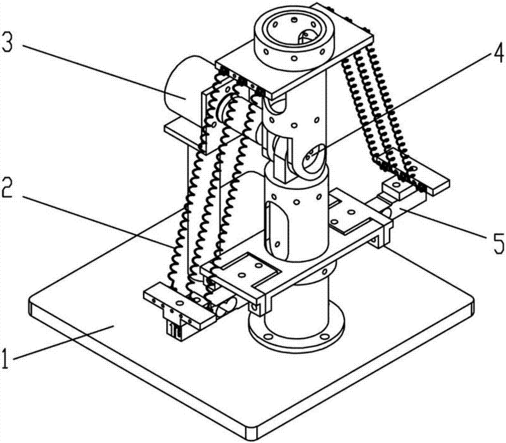
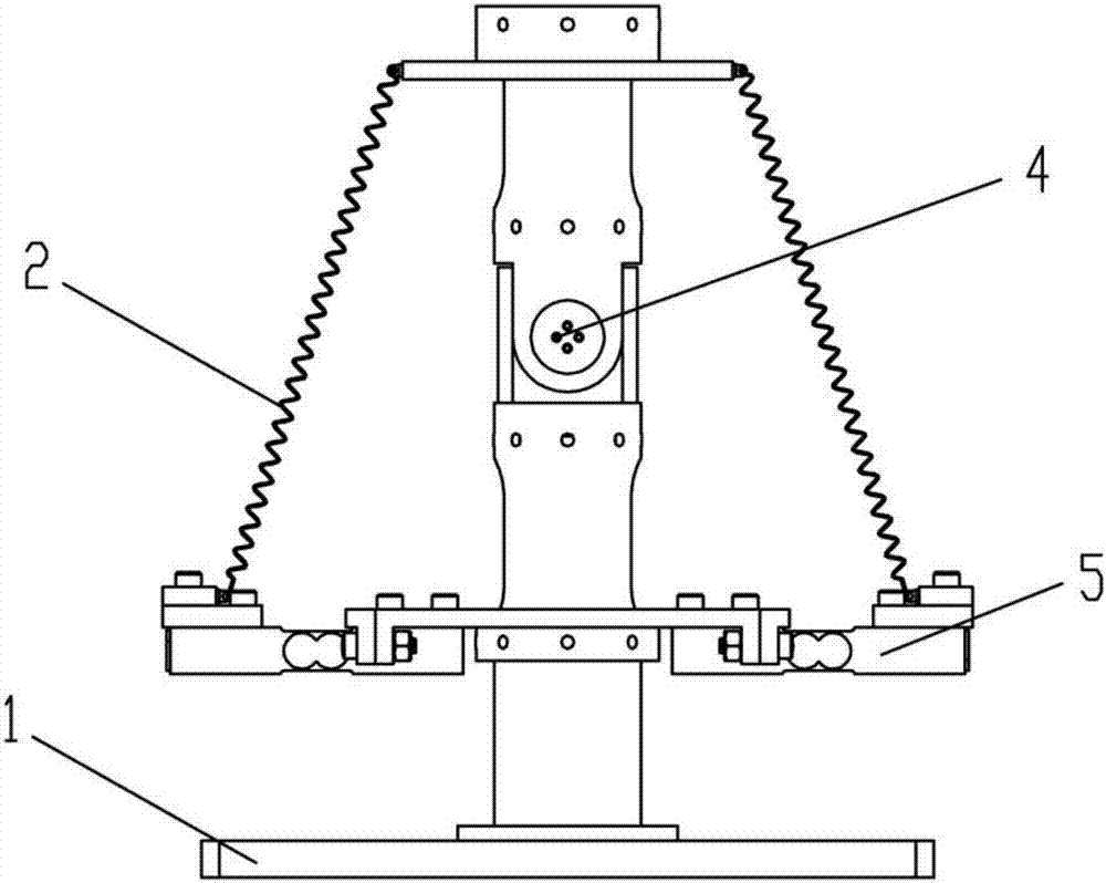
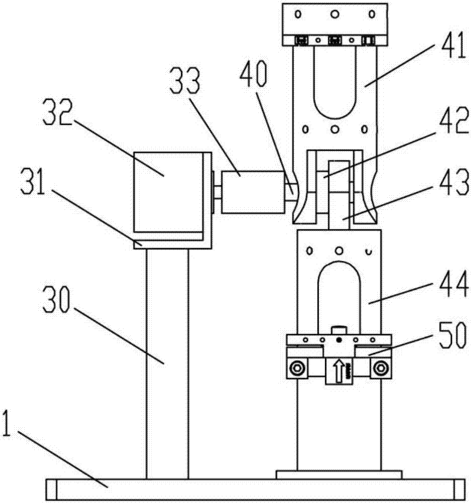
[0023] Such as figure 1 with Figure 5 As shown, a variable stiffness service robot joint according to the present invention includes a base 1, a drive unit 2, a position information collection unit 3, a rotary joint unit 4 and a driving force collection unit 5, a position information collection unit 3 and a rotary joint unit The upper ends of 4 are coaxially connected, the lower ends of the position information collection unit 3 and the rotary joint unit 4 are respectively fixed on the base 1, the driving force collection unit 5 is fixed on the rotary joint unit 4, and one end of the driving unit 2 is connected to the rotary joint unit 4, The other end is connected to the driving force acquisition unit 5. The driving unit 2 includes a shape memory alloy spring 20, an adjustable digital power supply, a voltage control module and a co...
PUM
 Abstract
Description
Claims
Application Information