Layered frame for launching vehicle

A layered, launch vehicle technology, applied in the frame field, can solve the problems of poor stability, heavy weight, high center of mass, etc., and achieve the effect of reducing the overall weight and increasing the load of the frame

Active Publication Date: 2017-10-13
BEIJING INST OF SPACE LAUNCH TECH +1
View PDF5 Cites 5 Cited by
  • Summary
  • Abstract
  • Description
  • Claims
  • Application Information

AI Technical Summary

Problems solved by technology

[0004] In order to solve the problems of heavy weight, high center of mass and poor stability in the frame of the launch vehicle in the prior art, the present invention provides a layered frame for the launch vehicle, which includes a bottom frame assembly, a middle frame assembly 1. The left top frame assembly and the right top frame assembly, the bottom frame assembly includes a plurality of first transverse connecting beams distributed at intervals along the front and rear directions, and the plurality of first transverse connecting beams pass through the first left longitudinal connecting beam and The first right longitudinal connecting beam is fixed by welding, the distance between the first left longitudinal connecting beam and the first right longitudinal connecting beam is smaller than the transverse width of the first transverse connecting beam, and the first transverse connecting beam is connected with the first left longitudinal connecting beam distributed symmetrically with the central axis of the first right longitudinal connecting beam;

Method used


Image

  • Layered frame for launching vehicle
  • Layered frame for launching vehicle
  • Layered frame for launching vehicle

Examples


Embodiment Construction

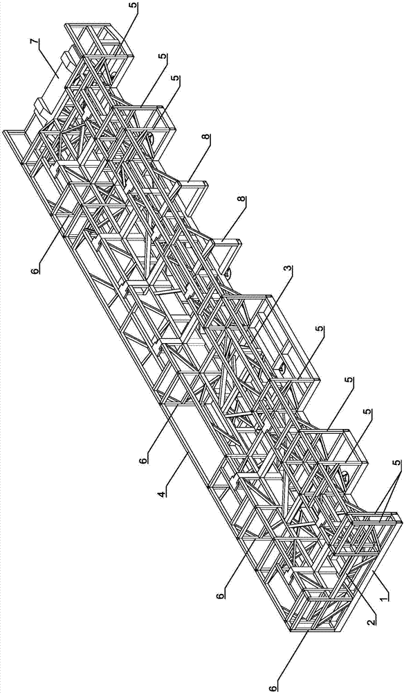
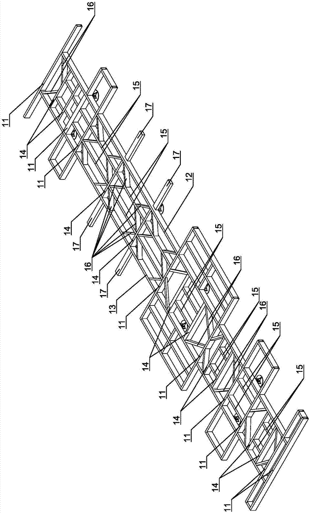
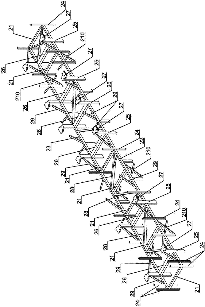
[0028] like Figure 1 to Figure 9 A specific embodiment of a layered frame for a launch vehicle of the present invention is shown, which is provided with a bottom frame assembly 1 , a middle frame assembly 2 , a left top frame assembly 3 and a right top frame assembly 4 . The bottom frame assembly 1 specifically includes a plurality of first transverse connection beams 11 spaced along the front-rear direction, and the plurality of first transverse connection beams 11 are welded and fixed by the first left longitudinal connection beam 12 and the first right longitudinal connection beam 13, Make the distance between the first left longitudinal connecting beam 12 and the first right longitudinal connecting beam 13 smaller than the lateral width of the first lateral connecting beam 11, and make the first lateral connecting beam 11 connect the beam 12 and the first The central axis of the right longitudinal connecting beam 13 is symmetrically distributed from left to right.

[002...


PUM


Abstract

The invention relates to a layered frame for a launching vehicle, which comprises a bottom framework assembly, a middle framework assembly, a left top layer framework assembly and a right top layer framework assembly; the middle layer framework assembly is welded and fixed with the bottom layer framework assembly through lower ends of a supporting upright post and a hanging upright post on a second left longitudinal connecting beam and a second right longitudinal connecting beam; the left top layer framework assembly and the right top layer framework assembly are welded and fixed with the upper ends of the supporting upright post and the hanging upright post; the left end and the right end of a first cross connecting beam of the bottom layer framework assembly are welded and fixed with the left top layer framework assembly, the right top layer framework assembly and the middle layer framework assembly through a left connector and a right connector correspondingly. The layered frame has the advantages of being light in weight, big in load, stable in structure, and relatively low in centroid; the safety of the launching vehicle and the high-speed driving stability are effectively improved.

Description

technical field [0001] The invention relates to a vehicle frame, in particular to a layered integrated vehicle frame for a launch vehicle. Background technique [0002] In the field of military and aerospace, the existing launch vehicle mainly adopts the structure of stacking the top-loading equipment compartment on the ordinary frame. The higher weight and higher center of mass affect the stability of high-speed driving. SUMMARY OF THE INVENTION [0003] The purpose of the present invention is to provide a layered frame for a launch vehicle, which has the advantages of light weight, large load, stable structure and low center of mass, and can effectively improve the safety of the launch vehicle and the stability of high-speed driving . [0004] In order to solve the problems of heavy weight, high center of mass and poor stability of the frame of the launch vehicle in the prior art, the present invention provides a layered frame for the launch vehicle, which includes a b...

Claims


Application Information

Patent Timeline
Patent Type & Authority Applications(China)
IPC IPC(8): B62D21/02B62D21/06F41F7/00
CPCB62D21/02B62D21/06F41F7/00
Inventor 丁丹刘相新李帅申焱华赵永涛黎兰张涛华黄宏伟蒋金超
Owner BEIJING INST OF SPACE LAUNCH TECH
Why Eureka
Try Eureka