

Disc lock type scaffold constructing system
A scaffolding and disc-locking technology, which is applied in the field of disc-locking scaffolding construction system, can solve the problems of inability to guarantee the overall stability of the scaffold, weak strength, and small bearing capacity of portal scaffolding
- Summary
- Abstract
- Description
- Claims
- Application Information
AI Technical Summary
Problems solved by technology
Method used
Image

Examples
Embodiment 1
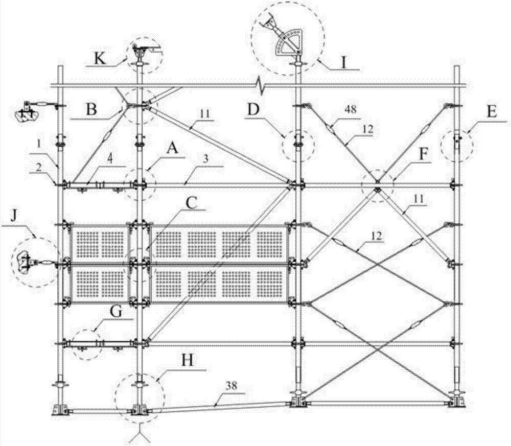
[0073] Embodiment 1: connection by twist lock;
[0074] The front end of the twist lock head is preferably an arc structure, which makes it closely connected with the vertical rod and is not easy to loosen.
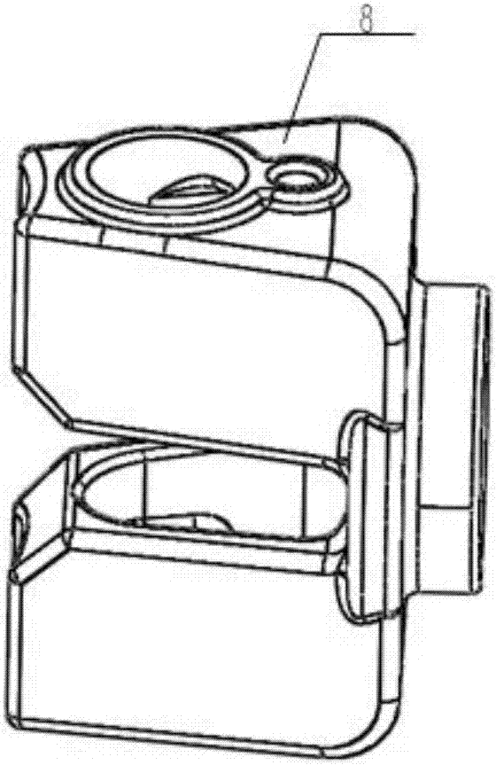
[0075] A hollow cylindrical connecting device is provided at the rear of the twist lock head to form a horizontal rod plug 8 of the twist lock. The horizontal rod can be fixedly connected to the cylindrical connecting device, and can be welded or riveted into an integral structure.
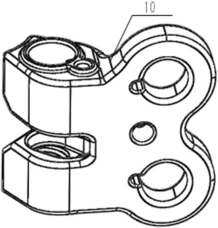
[0076] The rear part of the twist lock head is provided with an integrated plug-in structure to form a twist-lock oblique rod plug 10. The plug-in structure includes a plurality of connection holes, and the oblique rod is provided with an integrated oblique rod connector. 1101 and insertion part 1102, the base part 1101 is connected with the oblique rod, and the front end of the insertion part 1102 is provided with a pin hole 1103 or a limit protrusion 1104, and the integrated plug is inserte...
Embodiment 2
[0077] Embodiment 2: pin lock mode connection;
[0078] The pin lock mechanism includes a pin lock horizontal bar plug 7, a pin lock oblique bar plug 701, a flat pin 5 and a locking pin 6; the flat pin 5 is a wedge-shaped structure, and the bottom is provided with an anti-off rivet 502; the pin lock horizontal bar plug The rear part of the lock head of 7 is provided with a hollow cylindrical connecting device, and the horizontal bar can be fixedly connected in the cylindrical connecting device;
[0079] The rear part of the pin-lock oblique rod plug 701 is provided with an integrated plug-in structure, and the plug-in structure includes a plurality of connection holes. Base part 1101, insertion part 1102, the base part 1101 is connected with the oblique rod, the front end of the insertion part 1102 is provided with a pin hole 1103 or a limit protrusion 1104, and the integrated plug is inserted into the jack of the oblique rod connection part for connection, and the pin hole I...
Embodiment 3
[0083] Embodiment 3: safety protection system;
[0084] The safety net connection system includes a dust suppression / safety net 16, a dust suppression / safety net connection plug 14, and a latch 15;
[0085] The dust suppression / safety net connection platform 1403 is set on the dust suppression / safety net connection plug 14, and the frame of the dust suppression / safety net is provided with an upper intubation tube 18, a lower intubation tube 17 and a matching dust suppression / safety net plug 15. The dust suppression / safety net connection platform 1403 is provided with a main hole 1404 and a secondary hole 1405 for installation, and the upper intubation tube 18 and the lower intubation tube 17 of the dust suppression / safety net are respectively aligned with the dust suppression / safety net connection plug 14 The installation main hole 1404, insert and fix the dust suppression / safety net pin 15 from top to bottom; the dust suppression / safety net connection platform 1403 is provide...
PUM
 Abstract
Description
Claims
Application Information