
Joined synthetic resin body, and production method therefor

A technology of synthetic resin and manufacturing method, which can be applied to other household appliances, household components, engine lubrication, etc., and can solve the problems of prolonged and time-consuming welding operations, etc.

Inactive Publication Date: 2017-10-13
TAIHO INDUSTRIES CO LTD
View PDF5 Cites 4 Cited by
  • Summary
  • Abstract
  • Description
  • Claims
  • Application Information

AI Technical Summary

Problems solved by technology

[0005] However, in the synthetic resin bonded body described in Patent Document 1, in order to ensure joint strength by the welded portion, the welded portion requires a welded area greater than a certain amount.
Therefore, there is a problem that it takes time to melt the welded part, and the work time required for welding is prolonged.

Method used


Image

  • Joined synthetic resin body, and production method therefor
  • Joined synthetic resin body, and production method therefor
  • Joined synthetic resin body, and production method therefor

Examples


Embodiment Construction

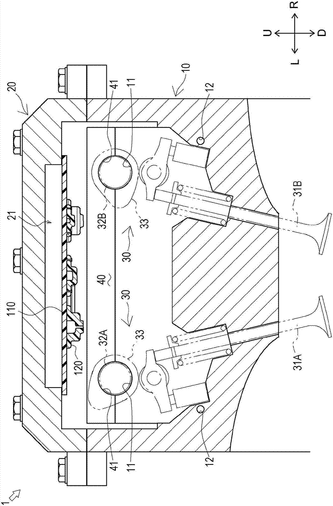
[0042] In the following, the directions indicated by arrow U, arrow D, arrow F, arrow B, arrow L and arrow R in the figure are respectively defined as upper direction, lower direction, front direction, rear direction, left direction and right direction to carry out illustrate.

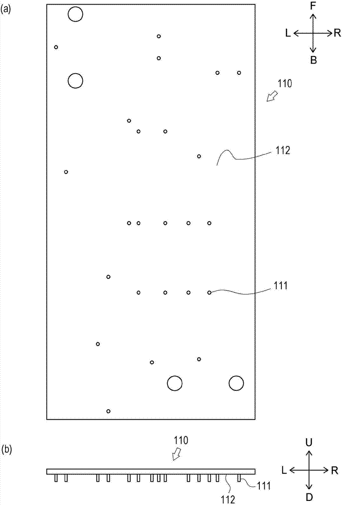
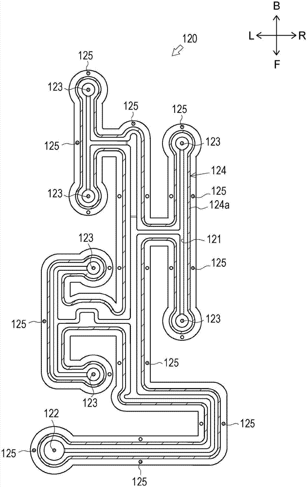
[0043] first use figure 1 , the configuration of the engine 1 including the baffle plate 110 and the oil passage forming member 120 according to one embodiment of the present invention will be described.

[0044] The engine 1 of the present embodiment includes valve mechanisms 30 , which will be described later, on the intake side and the exhaust side, respectively. Since the structure of the valve mechanism 30 is substantially the same on the suction side and the exhaust side, in the following, for the convenience of description, the structure on the exhaust side ( figure 1 The structure shown on the left side) will be described, and the structure on the suction side will be omitted appropriately ( ...


PUM


Abstract

Provided are: a joined synthetic resin body which is capable of ensuring both flow-path sealing properties and joining strength between synthetic resin components, even if the surface areas of regions to be welded are small; and a production method therefor. The joined synthetic resin body of the present invention is provided with: a baffle plate 110; an oil-path-forming member 120 which is in contact with the baffle plate 110; an oil path 130 which is formed between the baffle plate 110 and the oil-path-forming member 120, and in which a lubricating oil circulates; seal parts 140 which seal the periphery of the oil path 130 as a result of the baffle plate 110 and the oil-path-forming member 120 being welded together outside the oil path 130; and joining parts 150 which join the baffle plate 110 and the oil-path-forming member 120.

Description

technical field [0001] The present invention relates to a synthetic resin bonded body formed by welding synthetic resin members to each other and a method for manufacturing the same. Background technique [0002] Conventionally, a technique of a synthetic resin bonded body formed by welding synthetic resin members to each other is known. Such an example is described in Patent Document 1. [0003] Patent Document 1 describes a synthetic resin bonded body (laser welded structure) that includes a rectangular plate-shaped baffle disposed in a cylinder head cover of an engine, and a flow path forming member that is connected with the flow path forming member from below. The above-mentioned baffles contact (overlap) to form an oil passage. The baffle plate and the flow path forming member are welded to each other at a welded portion (contact surface of the flow path forming member) adjacent to the oil passage. [0004] In the synthetic resin bonded body thus constituted, the we...

Claims


Application Information

Patent Timeline
Patent Type & Authority Applications(China)
IPC IPC(8): B29C65/16B29C65/56
CPCB29L2031/749B29C65/1635B29C65/1677B29C65/18B29C65/606B29C66/112B29C66/114B29C66/131B29C66/21B29C66/242B29C66/244B29C66/5346B29C66/71B29C66/8322F01M13/04F02F7/006F01M1/08F01M9/10F01M11/02F01M13/0416B29C65/72B29K2067/006B29K2023/00B29K2067/00B29K2067/003B29K2023/06B29K2023/12B29K2077/00B29K2027/06B29K2027/12F01M2011/022F02F1/24
Inventor 上野友三川原贤大
Owner TAIHO INDUSTRIES CO LTD
Learn More