Fuel pump

A technology for fuel pumps and pump chambers, which is applied to pumps, liquid fuel feeders, liquid fuel engines, etc., and can solve problems such as pump efficiency decline

Active Publication Date: 2017-10-13
DENSO CORP
View PDF7 Cites 2 Cited by
  • Summary
  • Abstract
  • Description
  • Claims
  • Application Information

AI Technical Summary

Problems solved by technology

There is concern about a decrease in pump efficiency due to the above reasons

Method used


Image

  • Fuel pump
  • Fuel pump
  • Fuel pump

Examples


no. 1 Embodiment approach

[0040] Hereinafter, the first embodiment will be described based on the drawings.

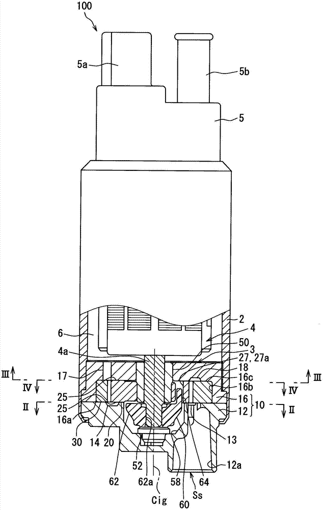
[0041] Such as figure 1 As shown, the fuel pump 100 of the first embodiment is a positive displacement trochoid pump mounted on a vehicle. The fuel pump 100 includes a side cover 5 protruding to the outside from an end opposite to the pump body 3 so as to sandwich the pump body 3 and the electric motor 4 housed inside the cylindrical pump body 2 in the axial direction. Here, the side cover 5 includes an electrical connector 5 a for supplying electricity to the electric motor 4 and a discharge port 5 b for discharging fuel. In such a fuel pump 100 , the rotation shaft 4 a of the electric motor 4 is rotationally driven by energization from an external circuit via the electrical connector 5 a. As a result, the fuel sucked and pressurized by the pump main body 3 by the rotational force of the rotary shaft 4 a of the electric motor 4 is discharged from the discharge port 5 b. In addition, the fu...

no. 2 Embodiment approach

[0092] Hereinafter, a second embodiment will be described based on the drawings.

[0093] Such as Figure 13 As shown, the fuel pump 101 of the second embodiment is a positive displacement trochoid pump mounted on a vehicle. The fuel pump 101 includes a side cover 105 protruding to the outside from an end opposite to the pump body 103 , sandwiching a pump body 103 and an electric motor 104 accommodated in a cylindrical pump body 102 in the axial direction. Here, the side cover 105 includes an electrical connector 105 a for supplying electricity to the electric motor 104 and a discharge port 105 b for discharging fuel. In such a fuel pump 101 , the rotary shaft 104 a of the electric motor 104 is rotationally driven by energization from an external circuit through the electrical connector 105 a. As a result, the fuel sucked and pressurized by the rotation of the external gear 130 and the internal gear 120 of the pump main body 103 is discharged from the discharge port 105b by ...


PUM


Abstract

A fuel pump is provided with an outer gear (30) having a plurality of inner teeth (32a), an inner gear (20) having a plurality of outer teeth (24a) and meshing eccentrically in an eccentric direction (De) with the outer gear, a pump housing (10) for rotatably accommodating the outer gear and the inner gear, an electric motor (4) having a rotating shaft (4a), and a joint member (60) for relaying the rotating shaft with the inner gear. The outer gear and the inner gear rotate while expanding and contracting the volumes of a plurality of pump chambers (40) formed between the two gears, whereby fuel is sequentially drawn into and discharged from the pump chambers. The inner gear has an insertion hole (27) recessed in the axial direction. The joint member has a main body part (62) that fits with the rotating shaft, a leg part (64) extending in the axial direction from the main body part and inserted into the insertion hole allowing a gap therebetween, and a protruding part (66) protruding from the leg part toward the rotationally advancing side of the inner gear and decreasing in width in the axial direction toward a peak part (66a).

Description

[0001] Cross-references to related applications [0002] This application is based on Japanese Patent Application No. 2015-13545 filed on January 27, 2015 and Japanese Patent Application No. 2015-82662 filed on April 14, 2015, and the descriptions thereof are incorporated herein by reference. technical field [0003] The present invention relates to a fuel pump that sequentially sucks fuel into each pump chamber and then discharges it. Background technique [0004] Conventionally, there is known a fuel pump that sequentially sucks fuel into each pump chamber and then discharges it. The fuel pump disclosed in Patent Document 1 includes: an external gear having a plurality of internal teeth; an internal gear having a plurality of external teeth meshing with (fitting) the external gear eccentrically in an eccentric direction; Rotatably accommodates; an electric motor having a rotationally driven rotary shaft. The external gear and the internal gear rotate while expanding and ...

Claims


Application Information

Patent Timeline
Patent Type & Authority Applications(China)
IPC IPC(8): F04C2/10F04C15/00
CPCF04C2/084F04C2/102F04C15/0073F04C2210/1044F04C2230/603F02M37/08F04C2/10F04C15/00F04C13/001F04C15/0061F04C15/008F04C2240/30F04C2240/40F04C2240/60
Inventor 酒井博美古桥代司
Owner DENSO CORP
Why Eureka
Try Eureka