Process pump having a crank drive

A process pump and crank mechanism technology, which is applied to the parts, pumps, and crankshafts of pumping devices used for elastic fluids, can solve problems such as increased fatigue failure, and achieve the effects of reduced vibration and uniform pumping rate

Inactive Publication Date: 2017-10-13
SPX FLOW TECH NORDERSTEDT
View PDF7 Cites 1 Cited by
  • Summary
  • Abstract
  • Description
  • Claims
  • Application Information

AI Technical Summary

Problems solved by technology

As an example, an increased likelihood of fatigue failure due to vibration is mentioned here

Method used


Image

  • Process pump having a crank drive
  • Process pump having a crank drive
  • Process pump having a crank drive

Examples


Embodiment Construction

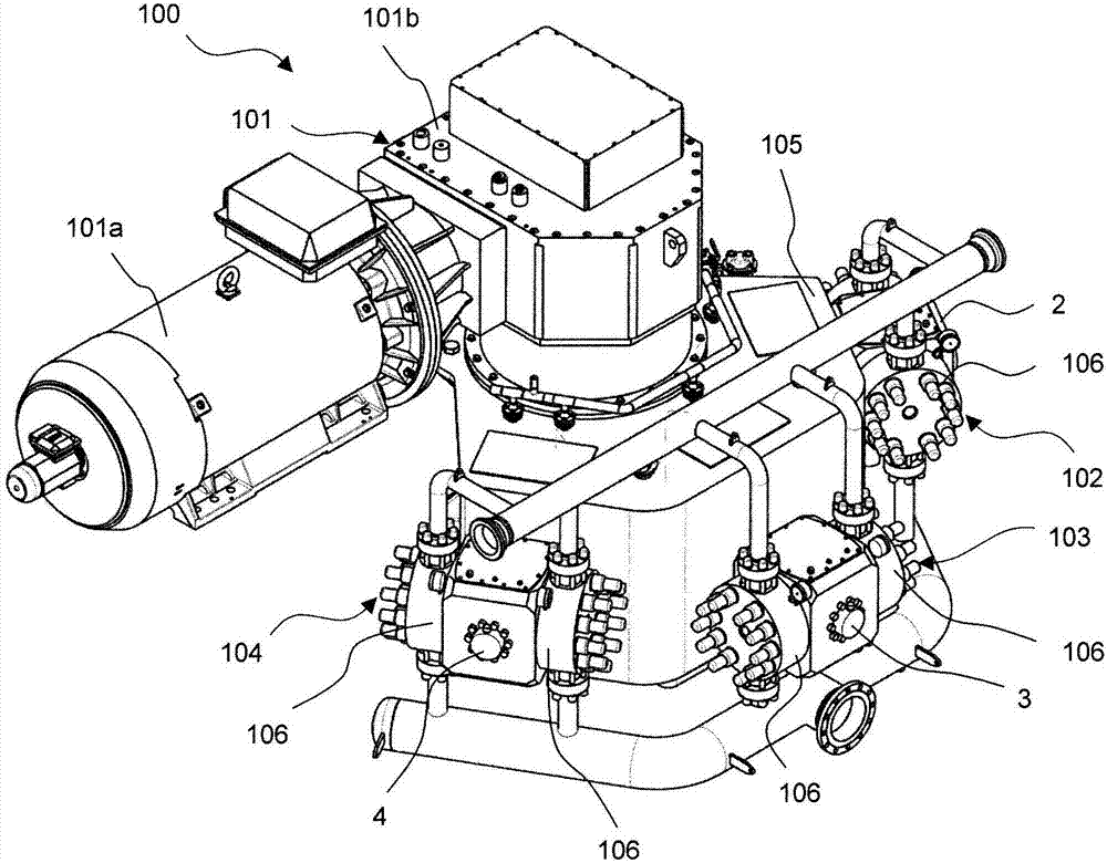
[0034] figure 1 A process pump 100 according to the invention is shown in . Process pump 100 has three barrels 2, 3, 4, respectively denoted as first barrel 2 ( figure 1 The most rear barrel), the second barrel 3 ( figure 1 middle barrel) and the third barrel 4 ( figure 1 in the front barrel). In the following, components labeled "first", "second", "third" or similar prefixes mean corresponding to the corresponding barrel 2, 3, 4.

[0035] In addition, if figure 1 As shown, the process pump 100 has double-acting pump heads 102, 103, 104 in addition to barrels 2, 3, 4, each double-acting pump head has two pump covers 106, and the piping leading to the suction or delivery line is covered. Mounts to pump cover. Furthermore, the process pump 100 has a drive device 101 (for example, an electric motor 101 a and a speed reducer 101 b ) and a housing 105 .

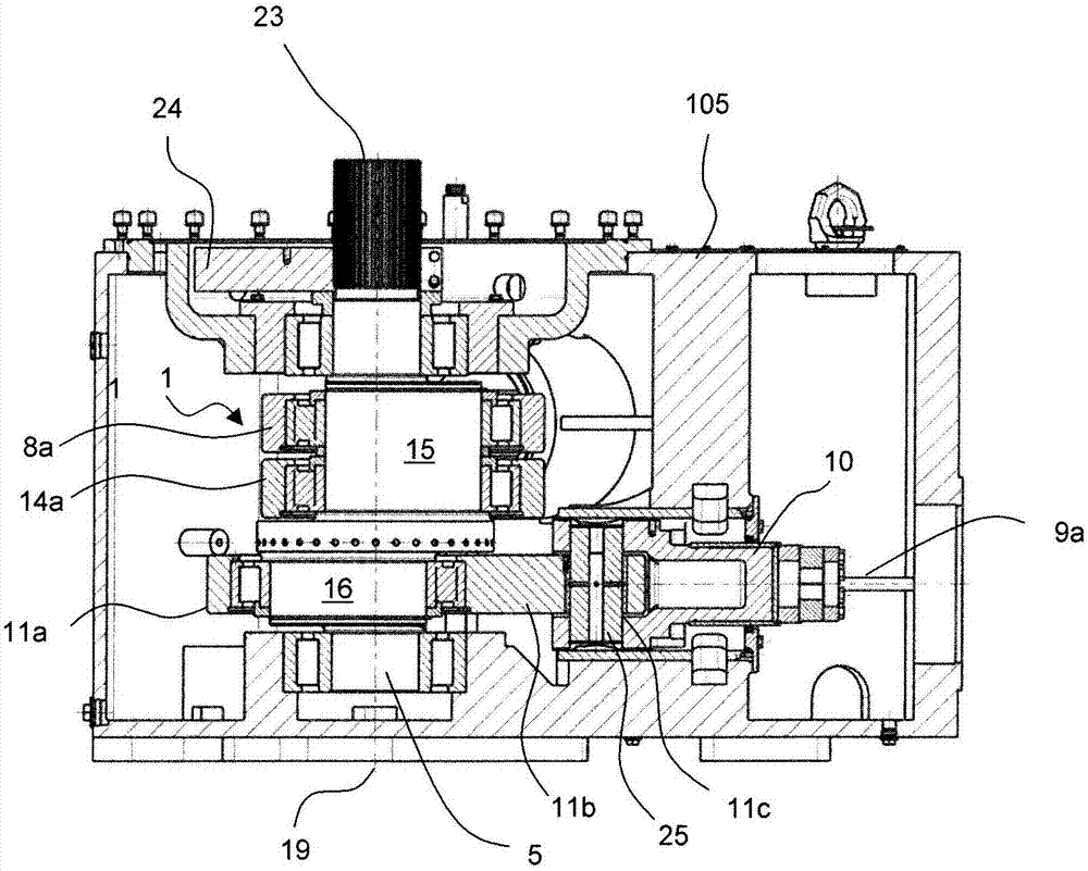
[0036] figure 2 A section through the housing 105 is shown in (the drive unit 101 is not shown). It can be seen how th...


PUM


Abstract

The present invention relates to a process pump having a crank drive (1) and having at least three cylinders, which, as viewed clockwise or counterclockwise about the crank drive (1), constitute a first cylinder, a second cylinder and a third cylinder, wherein the crank drive (1) has a vertical crankshaft and, for each cylinder, in each case one crosshead (7, 10, 13) and one connecting rod (8, 11, 14) with in each case one large connecting-rod eye (8a, 11a) for receiving the crankshaft, wherein the crossheads (7, 10, 13) are functionally connected to the crankshaft via the connecting rods (8, 11, 14). The invention is distinguished by the fact that the crankshaft is in the form of an eccentric shaft (5) with a first eccentric and a second eccentric, wherein the connecting rod (8) of the first cylinder and the connecting rod (14) of the third cylinder are arranged on the first eccentric, and wherein the connecting rod (11) of the second cylinder is arranged on the second eccentric, such that the large connecting-rod eye (8a) of the connecting rod (8) of the first cylinder and the large connecting-rod eye of the connecting rod (14) of the third cylinder have a common central axis.

Description

technical field [0001] The invention relates to a process pump with a crank mechanism. In particular, the invention relates to a process pump having a plurality of barrels, each barrel having a crosshead as connecting element to a connecting rod, wherein the crosshead is functionally connected to the crankshaft via the connecting rod. Background technique [0002] Typically, such process pumps with multiple barrels are used for high pumping rate pumping and / or high pressure pumping. A problem with such process pumps is the relatively large space requirement, since the pump heads have to be constructed at a certain distance from one another, especially when diaphragm pump heads are used. Process pumps are oscillating positive displacement pumps with a fixed stroke length. [0003] With known process pumps having a crank mechanism, the barrels are arranged in series in parallel and are supported along the crankshaft. In this case, the large barrel distance in the connection...

Claims


Application Information

Patent Timeline
Patent Type & Authority Applications(China)
IPC IPC(8): F16C3/06F16C7/02F04B53/00F04B9/04
CPCF04B9/045F04B53/006F16C7/023F04B9/04F16C7/02F04B1/00F04B1/143F04B53/144
Inventor 格奥尔格·罗森克兰茨托马斯·里尔克利斯汀·胡恩克
Owner SPX FLOW TECH NORDERSTEDT
Why Eureka
Try Eureka