Sewing anti-thread-breakage device of sewing machine

An anti-sewing device and technology for sewing machines are applied in sewing machine control devices, sewing machine components, and thread cutting mechanisms in sewing machines. The effect of hooking and returning the thread, not easy to jump off the thread, and reasonable space arrangement

Active Publication Date: 2017-10-17
JACK SEWING MASCH CO LTD
View PDF5 Cites 3 Cited by
  • Summary
  • Abstract
  • Description
  • Claims
  • Application Information

AI Technical Summary

Problems solved by technology

The assembly of the thread clamping device and the thread knife of the above-mentioned sewing machine takes up a large space. After the thread knife clamps the thread, it returns to the position away from the needle, the movement distance is long, and the movement stroke is large. During the second sewing process, Due to the large angle of the line crimping, the crimping effect is not good, so it is easy to cause the upper decorative thread to not be threaded and the stitches to skip, and the thread clamping force of the thread clamping device in the above sewing machine cannot be adjusted

Method used


Image

  • Sewing anti-thread-breakage device of sewing machine
  • Sewing anti-thread-breakage device of sewing machine
  • Sewing anti-thread-breakage device of sewing machine

Examples


Embodiment 1

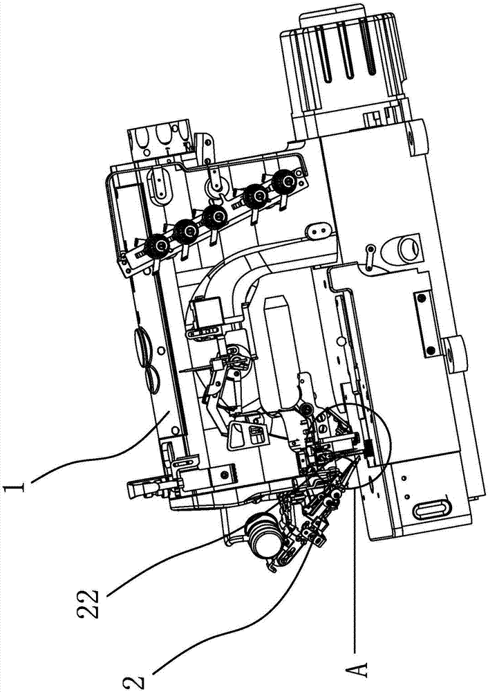
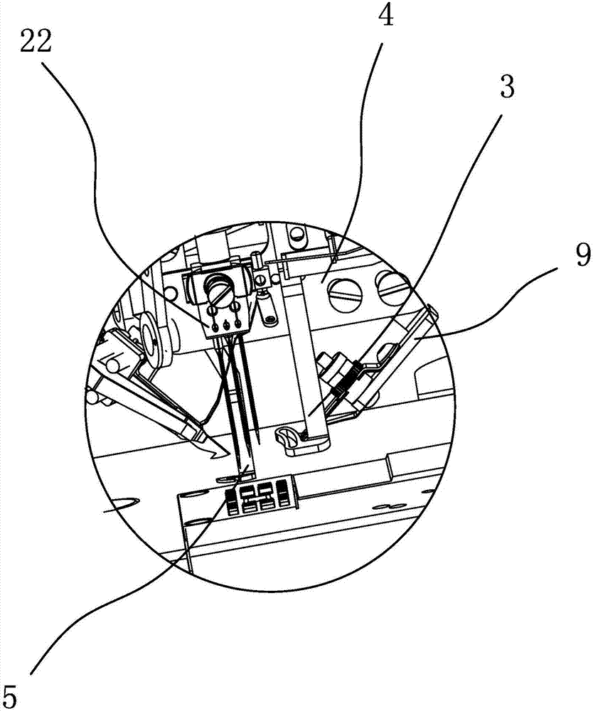
[0027] like figure 1 and 2 As shown, the sewing machine includes a casing 1, a decorative thread knife assembly 2, a needle feeding hook, a needle feeding frame 22 and a needle feeding thread plate 3. The seam prevention device includes a mounting plate 4, a wire pulling assembly and a thread clamping assembly. The mounting plate 4 is in the shape of a long strip. rear side.

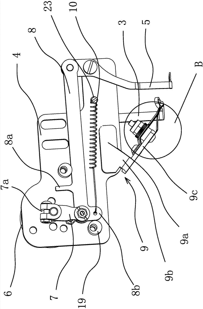
[0028] The wire pulling assembly includes a driving part and a wire pulling knife 5 with a pull hook at one end, and a driving crank 7 and a transmission connecting rod 8 are also arranged between the driving part and the wire pulling knife 5 of the driving part. like image 3 As shown, in the present embodiment, the driving part is a rotating electromagnet 6, and the rotating electromagnet 6 is fixed on one end of the mounting plate 4, and the middle part of the wire pulling knife 5 is hinged on the other end of the mounting plate 4 through a rotating shaft, and the rotating electromagnet 6 and Wiri...

Embodiment 2

[0034] The structure of this embodiment is basically the same as that of Embodiment 1, the difference is: Figure 5 As shown, the driving part is a linear electromagnet 20, the linear electromagnet 20 is fixed on the mounting plate 4, the iron core of the linear electromagnet 20 is fixed with a connecting pin 21, and one end of the driving crank 7 is provided with a strip-shaped sliding hole 7b. The connecting pin 21 slides through the sliding hole 7 b, the middle part of the driving crank 7 is hinged on the mounting plate 4 , and the other end of the driving crank 7 is hinged with the transmission connecting rod 8 . The mounting plate 4 also has a fixed column 23 , one end of the return spring 10 is fixedly sleeved on the fixed column 23 , and the other end is fixedly mounted on the driving crank 7 . The movement of the iron core of the linear electromagnet 20 drives the connecting pin 21, and the connecting pin 21 slides in the sliding hole 7b of the driving crank 7, and dri...


PUM


Abstract

The invention provides a sewing anti-thread-breakage device of a sewing machine, and belongs to the technical field of machinery. The problem that thread breakage is likely to happen to an existing sewing machine during sewing is solved. The sewing anti-thread-breakage device of the sewing machine comprises a mounting plate, a thread clamping assembly, a driving part and a thread drawing knife, the mounting plate is attached to the front end of a machine shell and is located on the rear side of a decorative thread cutter assembly, the driving part is fixed at one end of the mounting plate, and the middle of the thread drawing knife is hinged to the other end of the mounting plate; the two ends of a transmission connecting rod are hinged to the thread drawing knife and a driving crank respectively, and the driving part is connected with the driving crank; and a mounting piece is detachably connected to the portion, below the transmission connecting rod, of the mounting plate; the thread clamping assembly is fixed on the mounting piece and is opposite to the thread drawing knife, and a needle feeding and thread passing plate and the thread drawing knife are located on the two sides of the mounting plate respectively; a pulling hook of the thread drawing knife is not higher than the bottom of the needle feeding and thread passing plate, and a return spring is further arranged on the mounting plate. After the thread drawing knife of the sewing anti-thread-breakage device returns to the original position, the pulling hook is just located on the right side or the lower right portion of the needle feeding and thread passing plate, sewing is more stable, and skipped stitches and thread breakage are not likely to occur.

Description

technical field [0001] The invention belongs to the technical field of machinery and relates to a sewing machine anti-off device. Background technique [0002] At present, the operation process of the sewing machine will first complete the threading of the suture, and then press the cloth or clothing to be sewed with the presser foot, and finally use the needle to perform the sewing operation. Wherein, when wanting to suspend the sewing operation and take off the cloth or clothing, the upper decorative thread remaining on the cloth or clothing must be cut off, so that the cloth or clothing can be further taken off. However, in the process of cutting the upper trim in the early days, the operator had to pull out the seam with bare hands, and at the same time pull out the seam and reserve a section of seam for the convenience of the next sewing operation, and finally use scissors to pull out the seam. Sutures cut. However, the thread ends after cutting will stay near the sew...

Claims


Application Information

Patent Timeline
Patent Type & Authority Applications(China)
IPC IPC(8): D05B65/06D05B47/00D05B69/02D05B69/10
CPCD05B47/00D05B65/06D05B69/02D05B69/10
Inventor 李卫超洪建敏王志田国兵
Owner JACK SEWING MASCH CO LTD
Why Eureka
Try Eureka