Amphibious sewage pump

A technology for amphibious and sewage pumps, applied to pumps, pump components, components of pumping devices for elastic fluids, etc., can solve the problem of motor winding insulation breakdown and short-circuit burning, failure to pump special areas, and limited use range Limitation and other problems, to achieve the effect of convenient operation and maintenance, flexible use method, and good cleaning effect

Active Publication Date: 2017-10-17
ANSTEEL GRP MINING CO LTD
View PDF7 Cites 0 Cited by
  • Summary
  • Abstract
  • Description
  • Claims
  • Application Information

AI Technical Summary

Problems solved by technology

However, due to the characteristics of its own structure, the motor of the sewage submersible pump is located in the upper part of the pump body, while the impeller and water suction port of the water pump are located in the lower part of the pump body, so the sewage submersible pump is required to be used vertically and the depth of the sewage water level must be higher than that of the pump. Because the water level is lower than that of the water pump motor for a long time, the water pump motor will cool and dissipate heat due to no water immersion, which will cause the temperature of the water pump motor winding to be too high, causing the insulation breakdown of the motor winding and short-circuit burning, so the sewage submersible pump cannot pump water. Sewage below the height of the pump motor, that is, low water level sewage below 400mm
Moreover, the sewage submersible pump has no self-priming function, so it cannot be pumped due to the volume and weight limitations of the sewage submersible pump, which cannot be put into the special area for use in water, so its application range is limited.

Method used


Image

  • Amphibious sewage pump
  • Amphibious sewage pump
  • Amphibious sewage pump

Examples


Embodiment Construction

[0020] The specific implementation manner of the present invention will be further described below in conjunction with the accompanying drawings.

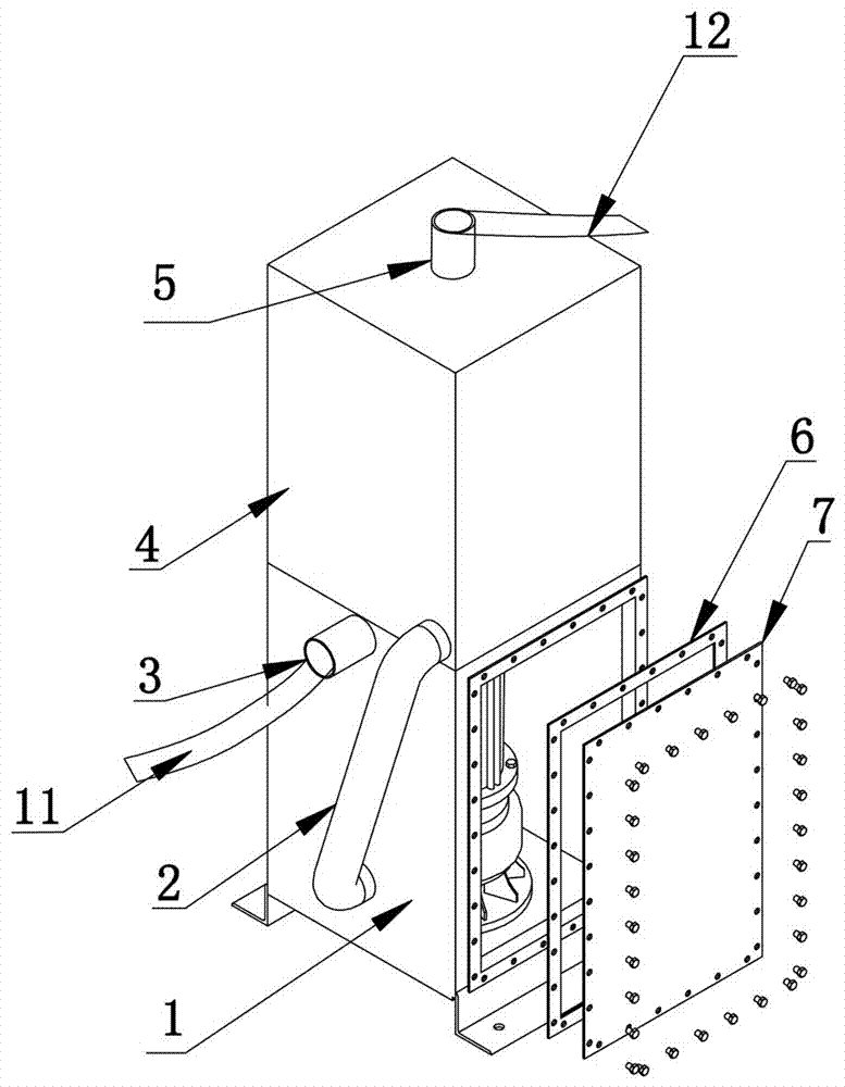
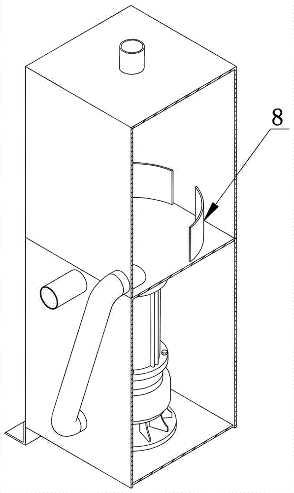
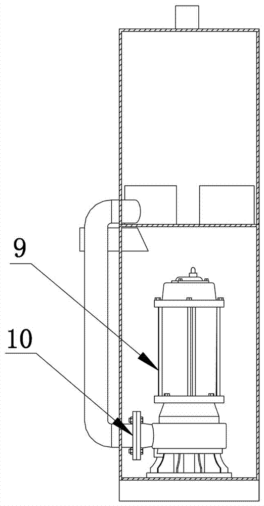
[0021] Such as figure 1 , 2 As shown in and 3, an amphibious sewage pump of the present invention includes a sewage submersible pump 9, and an outlet flange 10 arranged at the outlet of the sewage submersible pump 9 is characterized in that it also includes an upper box body 4 and a lower box body 1, the middle pipe 2 connecting the upper box 4 and the lower box 1, the water suction pipe 3 located on the top side wall of the lower box 1 and communicating with the lower box 1, and The guide pipe I11 connected to the water suction pipe 3, the drain pipe 5 arranged on the top of the upper box body 4, the guide pipe II12 connected to the drain pipe 5, the guide pipe arranged in the upper box body 4 Flow plate group, the sewage submersible pump 9 is sealed in the lower box 1 by the sealing cover 7 and the sealing gasket 6, the sewage ...


PUM


Abstract

The invention belongs to the technical field of sewage pump equipment, and particularly relates to an amphibious sewage pump. The amphibious sewage pump comprises a sewage submersible pump and an outlet flange which is arranged in an outlet of the sewage submersible pump. The amphibious sewage pump is characterized in that the amphibious sewage pump further comprises a combination box body consisting of an upper box body and a lower box body, a middle pipe which connecting the upper box body with the lower box body, a water absorbing pipe which located on the side wall of the top of the lower box body and communicates with the lower box body, a flow guide pipe which is connected with the water absorbing pipe, a water draining pipe arranged on the top of the upper box body and a flow guide plate assembly arranged in the upper box body, and the sewage submersible pump is sealed in the lower box body by a sealing cover and a sealing washer. According to the amphibious sewage pump, in the working process, a water pump motor always contains flowing water to cool the motor down, the problem of motor heat dissipation of the sewage submersible pump in the process of low water level pumping is solved, and the amphibious function is achieved.

Description

technical field [0001] The invention belongs to the technical field of sewage pump equipment, in particular to an amphibious sewage pump. Background technique [0002] In industrial production, sewage submersible pumps are widely used due to their compact structure, easy movement and no special requirements for water quality. However, due to the characteristics of its own structure, the motor of the sewage submersible pump is located in the upper part of the pump body, while the impeller and water suction port of the water pump are located in the lower part of the pump body, so the sewage submersible pump is required to be used vertically and the depth of the sewage water level must be higher than that of the pump. Because the water level is lower than that of the water pump motor for a long time, the water pump motor will cool and dissipate heat due to no water immersion, which will cause the temperature of the water pump motor winding to be too high and cause the insulatio...

Claims


Application Information

Patent Timeline
Patent Type & Authority Applications(China)
IPC IPC(8): F04D29/42F04D29/44F04D29/58
CPCF04D29/426F04D29/445F04D29/5806
Inventor 张岩王晓群于仁峰李满香
Owner ANSTEEL GRP MINING CO LTD
Why Eureka
Try Eureka