Binocular vision sensor on-site calibration method and binocular vision sensor on-site calibration device in complicated environment

A binocular vision and on-site calibration technology, which is applied in the direction of measuring devices, optical devices, instruments, etc., to achieve the effects of flexible and adjustable directions, flexible structure, and improved calibration efficiency

Active Publication Date: 2017-10-17
BEIHANG UNIV
View PDF6 Cites 34 Cited by
  • Summary
  • Abstract
  • Description
  • Claims
  • Application Information

AI Technical Summary

Problems solved by technology

How to realize simple and fast on-site sensor calibration is the key problem of visual measurement in the current complex environment

Method used


Image

  • Binocular vision sensor on-site calibration method and binocular vision sensor on-site calibration device in complicated environment
  • Binocular vision sensor on-site calibration method and binocular vision sensor on-site calibration device in complicated environment
  • Binocular vision sensor on-site calibration method and binocular vision sensor on-site calibration device in complicated environment

Examples


Embodiment Construction

[0025] The present invention will be further described below in conjunction with the accompanying drawings and specific embodiments.

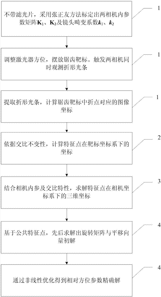
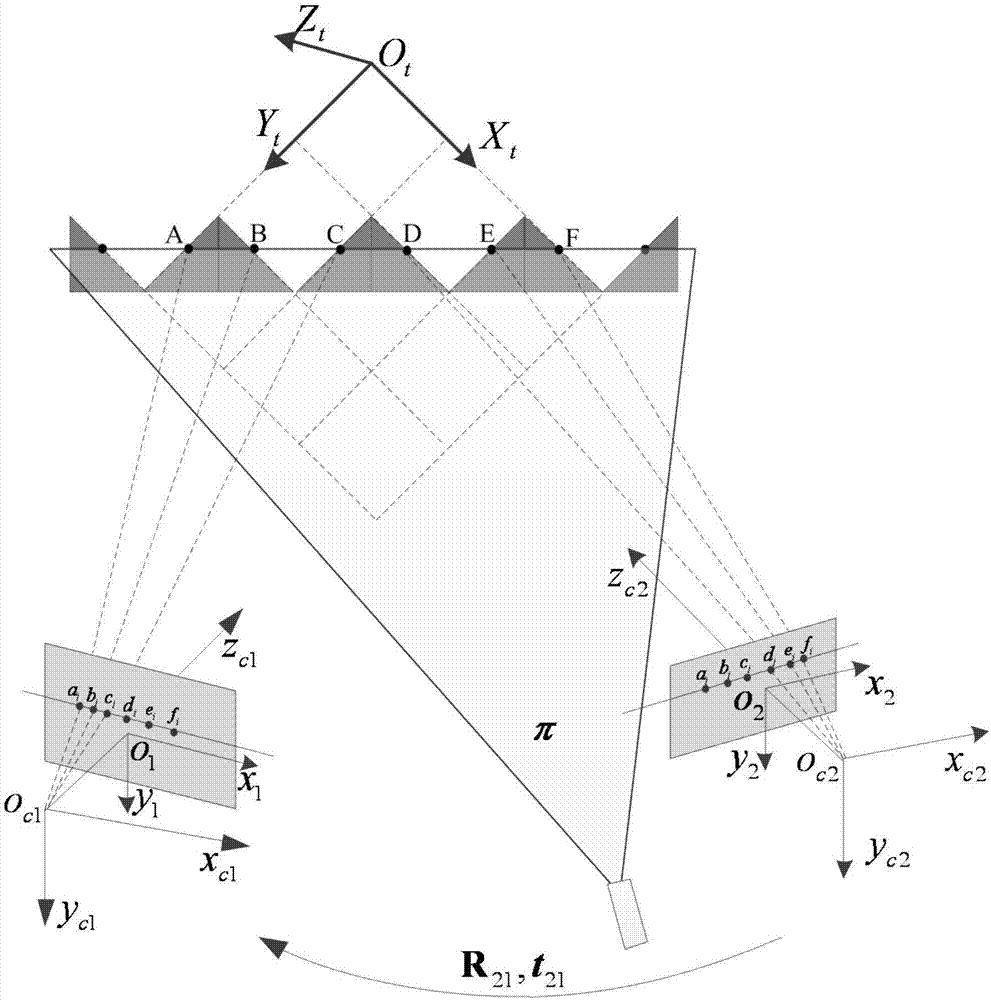
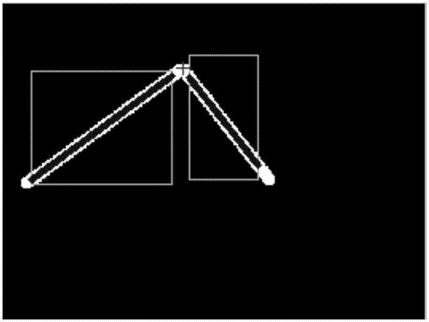
[0026] This method first uses the literature [3] (Zhang Z.A Flexible New Technique for CameraCalibration[J].IEEE Transactions on Pattern Analysis & Machine Intelligence, 2000,22(11):1330-1334.) to calibrate the internal parameters of the two cameras, and then extract the The laser and the sawtooth target form the image coordinates of the inflection points; at the same time, according to the image feature points, use the cross-ratio invariance to solve the coordinate values ​​of the feature points in the target coordinate system; calculate the target according to the relationship between the spatial straight line direction and the image blanking point The three-dimensional coordinates of the feature points in each camera coordinate system; and then solve the relative external parameters of the two cameras, including the rotation matrix and transl...


PUM


Abstract

The invention discloses a binocular vision sensor on-site calibration method and a binocular vision sensor on-site calibration device in complicated environment. A sawtooth target capable of moving freely is cooperated with a linear laser having a wavelength corresponding to that of an optical filter to complete on-site rapid calibration. According to light strip information irradiated on the target, an image coordinate of a characteristic break point formed by a light strip and the sawtooth target is determined. Based on cross-ratio invariability, the coordinates of all of the break points in a target coordinate system are determined, and by combining with internal parameters of video cameras, the three-dimensional coordinates of all of the target characteristic points in the coordinate systems of the video cameras are calculated, and therefore an external parameter initial value between the two video cameras is calculated. By an integral non-linear optimization, the exact solution of the external parameter between the two video cameras is acquired. An important practical application value is provided for solving a problem of multi-vision sensor global calibration in the complicated environment.

Description

technical field [0001] The invention relates to the technical field of on-site calibration of binocular vision sensors, in particular to a method and device for on-site calibration of binocular vision sensors in complex environments. Background technique [0002] Vision measurement systems are being widely used in complex environments, such as on-line measurement systems for geometric dimensions of train wheelsets, pantographs, and forgings. Usually, these visual measurement systems will install a filter in front of the camera lens to ensure the image quality and improve the stability of the measurement. However, this makes the global calibration of multiple sensors in complex lighting environments more and more difficult. For example, the on-line dynamic tester for the geometric dimensions of train wheels is composed of multiple groups of structured light vision sensors, which are respectively installed at different positions of the wheels at the trigger position to observ...

Claims


Application Information

Patent Timeline
Patent Type & Authority Applications(China)
IPC IPC(8): G01B11/00
CPCG01B11/00
Inventor 刘震潘晓武群
Owner BEIHANG UNIV
Why Eureka
Try Eureka