A combined cable tray

A cable tray and combined technology, which is applied to electrical components and other directions, can solve the problems of insufficient cooling of cables, cluttered cables, and difficulties in cable racking, etc., to achieve high installation efficiency, beautiful layout, and improved quality and installation. The effect of efficiency

Active Publication Date: 2018-10-12
镇江昌达电气有限公司
View PDF5 Cites 0 Cited by
  • Summary
  • Abstract
  • Description
  • Claims
  • Application Information

AI Technical Summary

Problems solved by technology

When cable laying requires the use of bridges, there are the following disadvantages. First, when faced with multi-fork intersections and complex and changeable project erection environments, the bridge installation cannot change the shape of the facility, and it is difficult to mount the cables and difficult to install. After installation, the style is not beautiful, and the placement of the cables is very messy; second, the existing cable bridges usually punch out ventilation holes on the bottom and sides, and use the external natural wind to heat the cables inside the bridge. However, from the actual effect, The cables are not sufficiently cooled, and it is prone to fire after a long time

Method used


Image

  • A combined cable tray
  • A combined cable tray
  • A combined cable tray

Examples


Embodiment Construction

[0056] The present invention will be further described below in conjunction with the accompanying drawings and specific embodiments.

[0057] In the description of the present invention, it should be noted that the terms "center", "upper", "lower", "left", "right", "vertical", "horizontal", "inner", "outer" etc. The indicated orientation or positional relationship is based on the orientation or positional relationship shown in the drawings, and is only for the convenience of describing the present invention and simplifying the description, rather than indicating or implying that the referred device or element must have a specific orientation, or in a specific orientation. construction and operation, therefore, should not be construed as limiting the invention. In addition, the terms "first", "second", and "third" are used for descriptive purposes only, and should not be construed as indicating or implying relative importance.

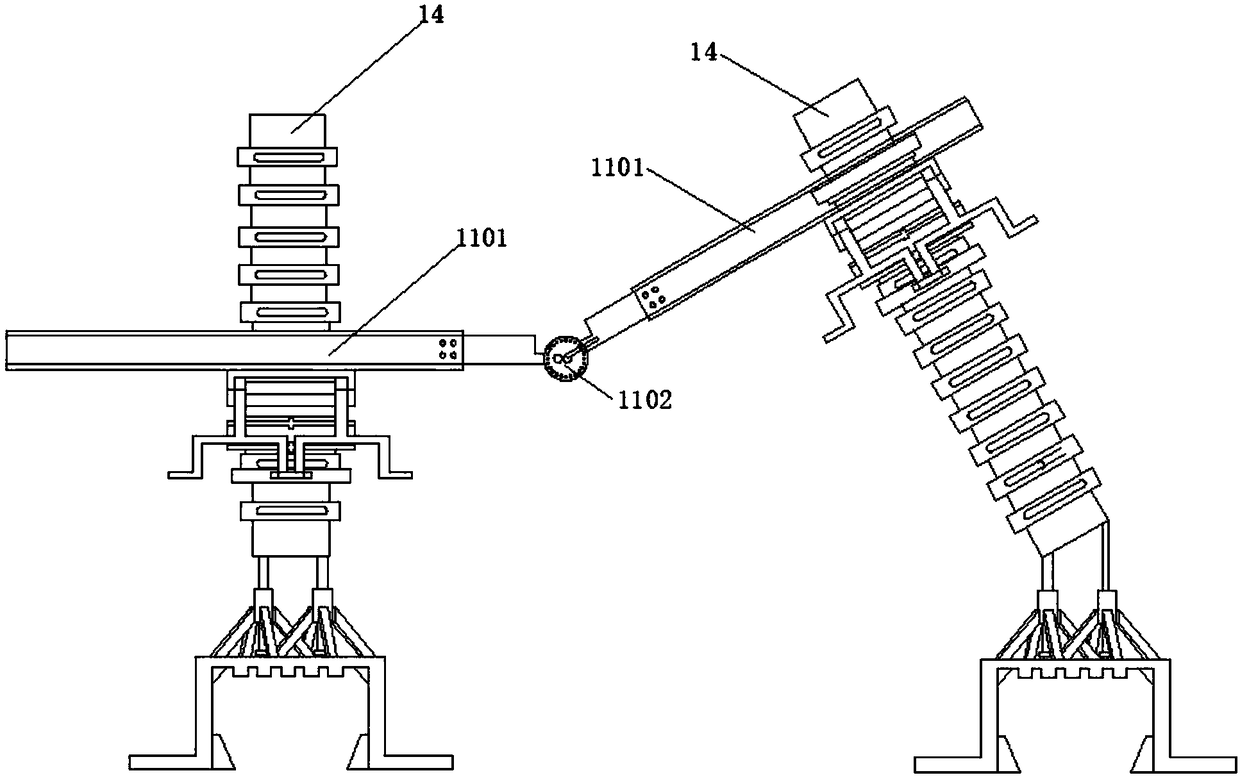
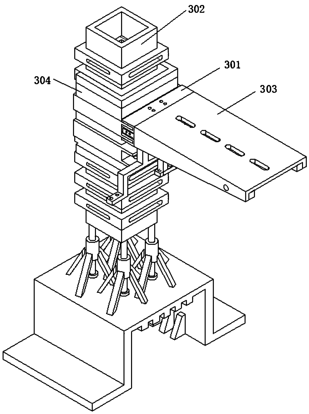
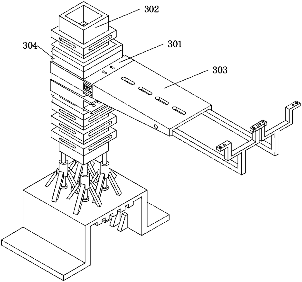
[0058] A combined cable tray, including a suppor...


PUM


Abstract

The invention provides a combined-type cable bridge stand. Through cooperation usage of a matched stand column, a bridge arm and a connection component, a purpose of rapid installation is reached. Installation is simple, assignment is beautiful, and installation quality and installation efficiency are increased. A bolt is used to connect an adjusting support and 360 degree rotation of the adjusting support is realized so that a contact area of a supporting arm and the bridge stand can be increased, hoisting of the supporting arm after rotation is realized and bending-resistance and torsion-resistance mechanical performance of the supporting arm is optimized. A plurality of plug grooves on the stand column are used to provide a plurality of different heights for the supporting arm, and the height of the supporting arm can be adjusted up and down according to a height of cable laying. At an occasion where the bridge stand needs to be laid at different heights before and after a cable, when the bridge stand needs to be arranged in an inclined mode, inclination arrangement can be realized through adjusting a lifting device. According to an actual condition of a site landform, flexible assembling can be performed, orientations and lengths are changed from multiple angles, an obstacle is avoided, multi-angle adjusting can be completed and a steering function in a cable line is realized.

Description

technical field [0001] The invention relates to the field of oil purifiers, in particular to a combined cable bridge. Background technique [0002] The cable tray product is a new type of cable laying device developed by industrially developed countries in the early 1960s. With the high development of electrification and automation, especially the change of power distribution mode, the direct burial of trenches and the laying of cables on brackets can no longer meet the requirements of use, and they are replaced by cable trays, thus speeding up the construction progress, ensuring quality, and realizing product quality. Standardization, serialization, generalization. Cable tray is a device for fixing cables, widely used in petroleum, chemical industry, electric power, light industry, telecommunications and other industries, mainly used for the laying of overhead power cables, control cables, lighting lines, and telecommunication cables. Commonly used bridges are generally m...

Claims


Application Information

Patent Timeline
Patent Type & Authority Patents(China)
IPC IPC(8): H02G3/04
CPCH02G3/0456
Inventor 郭力嘉郭如海崔正生
Owner 镇江昌达电气有限公司
Why Eureka
Try Eureka