

Device And Method For Mixing And Storing Polymethyl Methacrylate Bone Cement With Pressure Pump And Ampoule Breaker
A technology of polymethyl methacrylate and bone cement, applied in the field of monomer liquid and cement powder device, mixed bone cement, mixed polymethyl methacrylate bone cement, can solve the problems of complex structure and the like
- Summary
- Abstract
- Description
- Claims
- Application Information
AI Technical Summary
Problems solved by technology
Method used
Image

Examples
Embodiment Construction
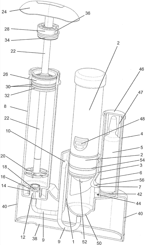
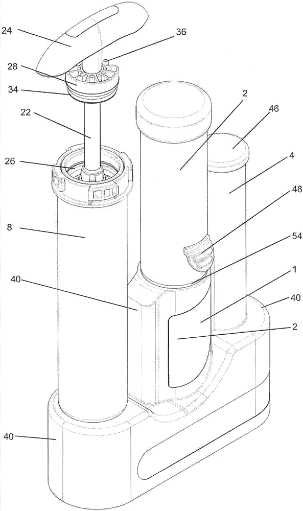
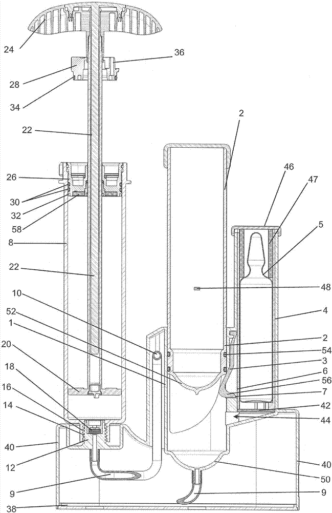
[0174] Figures 1 to 6 A device according to the invention for mixing polymethylmethacrylate bone cement and for storing the parent components of said bone cement, in particular monomer liquid and cement powder, is shown in different views The first exemplary embodiment of . The device is suitable for carrying out the method according to the invention.
[0175] The device comprises a hollow cylinder 1 in which a pump plunger 2, cylindrical in some regions, is arranged so as to be axially displaceable. An opening device 3 in the form of a short lever 3 is mounted at the outer side wall of the hollow cylinder 1 so as to be pivotable about an axis perpendicular to the axial direction of movement of the pump plunger 2 . A recess in the form of a window is located in the cylinder housing of the hollow cylinder 1 in the region of the joystick 3, through which window the joystick 3 is in the initial position ( Figures 1 to 3 ) extends into the interior of the hollow cylinder 1 . ...
PUM
 Abstract
Description
Claims
Application Information