Waste material discharging device and stamping die system

A technology of discharge device and stamping die, which is applied in the direction of pushing out equipment, etc., can solve the problems of insufficient waste discharge, inability to discharge waste, limited movement frequency, etc., to achieve rapid and effective discharge, increase movement frequency, and improve efficiency.

Pending Publication Date: 2017-10-20
AUX AIR CONDITIONING LTD BY SHARE LTD
View PDF7 Cites 2 Cited by
  • Summary
  • Abstract
  • Description
  • Claims
  • Application Information

AI Technical Summary

Problems solved by technology

However, there are some problems with this technology. For example, there are restrictions on the placement angle of the waste box, which is between 30° and 60°
In actual production, due to stamping equipment and other reasons, the placement angle of the waste box cannot be between 30° and 60°; the movement freque

Method used


Image

  • Waste material discharging device and stamping die system
  • Waste material discharging device and stamping die system
  • Waste material discharging device and stamping die system

Examples


Example

[0033] first embodiment

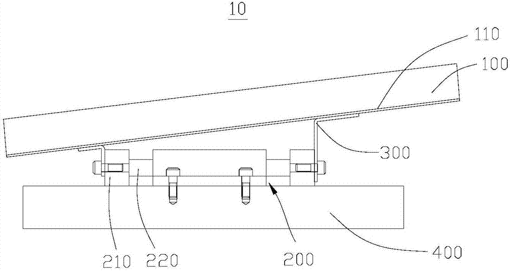
[0034] see figure 1 , the present embodiment provides a waste material discharge device 10, which is applied to the discharge of waste materials from stamping dies (not shown in the figure), which can quickly and effectively discharge the waste materials falling on the waste material discharge device 10, avoiding the accumulation and blockage of waste materials technical problems.

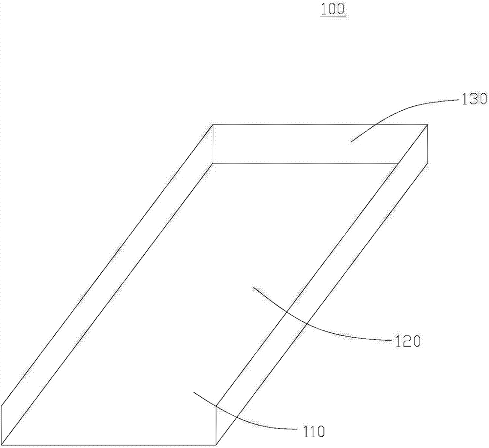
[0035] The waste material discharge device 10 includes a receiving structure 100 and a power unit 200, wherein the power unit 200 includes a movable part 210 and a guide structure 220, the movable part 210 is connected with the guide structure 220, and the movable part 210 can do linear reciprocating motion along the guide structure 220, accepting The structure 100 is fixedly connected with the movable part 210 , so that the receiving structure 100 can follow the movable part 210 to make linear reciprocating motion along the guide structure 220 . In addition, the receivi...

Example

[0049] Second Embodiment

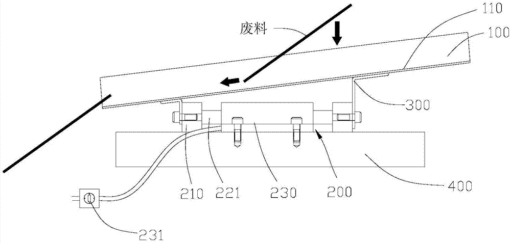
[0050] This embodiment provides a stamping die system (not shown), which adopts the waste discharge device 10 provided in the first embodiment, which can quickly and effectively discharge the waste falling on the waste discharge device 10, Avoid technical problems with clogging of waste accumulation.

[0051] Wherein, the stamping die system includes a stamping die (not shown) and a waste discharge device 10 . The stamping die includes an upper die (not shown) and a lower die (not shown). The upper die can reciprocate relative to the lower die. The upper die can selectively cooperate with the lower die to process products and generate waste, or the upper die is far away from the lower die. die in preparation for the next machining. And the stamping die can discharge the waste material along the first direction. In this embodiment, the movement of the waste discharge device 10 and the movement of the upper die are independent of each other, that is...


PUM


Abstract

The invention discloses a waste material discharging device and a stamping die system, and relates to the field of dies. The provided waste material discharging device is applied to discharging of stamping die waste materials and comprises a receiving structure and a power device. The power device comprises a movable piece and a guide structure. The movable piece is connected with the guide structure and can do linear reciprocating motion along the guide structure. The receiving structure is fixedly connected with the movable piece and provided with a receiving surface used for receiving the waste materials. The extension direction of the guide structure and the receiving surface form an acute angle. The invention further provides the stamping die system. The stamping die system adopts the waste material discharging device. According to the waste material discharging device and the stamping die system which are provided by the invention, the waste materials falling on the waste material discharging device can be rapidly and effectively discharged, and the technical problem of waste material accumulation and blocking is solved.

Description

technical field [0001] The invention relates to the field of moulds, in particular, to a waste discharge device and a stamping die system. Background technique [0002] In the prior art, the waste produced by the stamping die is usually guided through an inclined plane fixed below the stamping die for the waste to be discharged, but in the above-mentioned technology, waste materials with large or small volumes will accumulate and block the guiding inclined plane, making Waste discharge presents a huge problem. [0003] And in the prior art, in order to solve the above problem, adopted to make guide inclined-plane and the upper die linkage of stamping die, make guide inclined-plane can rotate around the lower side, waste material is thrown out. However, there are some problems in this technology, for example, there is a limit to the placement angle of the waste box, which is between 30° and 60°. In actual production, due to stamping equipment and other reasons, the placemen...

Claims


Application Information

Patent Timeline
IPC IPC(8): B21D45/04
CPCB21D45/04
Inventor 李国柱陈彬茜
Owner AUX AIR CONDITIONING LTD BY SHARE LTD
Why Eureka
Try Eureka