Calibration method for robot joint and calculating device
A technology of robot joints and calibration methods, applied in measurement devices, instruments, manipulators, etc., can solve problems such as low efficiency of calibration solutions, and achieve the effects of safe and reliable calibration process, high calibration efficiency, and improved accuracy
- Summary
- Abstract
- Description
- Claims
- Application Information
AI Technical Summary
Problems solved by technology
Method used
Image

Examples
Embodiment Construction
[0019] Embodiments of the present invention will be described in detail below with reference to the accompanying drawings.
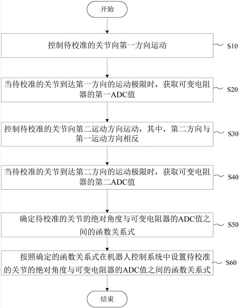
[0020] figure 1 is a flowchart illustrating a calibration method of a robot joint according to an embodiment of the present invention. The method for controlling smart home appliances according to the embodiments of the present invention can be applied to various electronic devices with automatic control functions, such as industrial computers, programmable controllers, and single-chip microcomputers.
[0021] The position feedback sensor of the robot joint according to the present invention may include various sensors capable of feeding back position information. For example, the position feedback sensor may include a variable resistor, and the variable resistor is mounted on the motor output shaft of the joint directly or through gears, and the position information of the joint is fed back by the variable resistor during the movement of the robot. Fo...
PUM
 Abstract
Description
Claims
Application Information
 - R&D
- Intellectual Property
- Life Sciences
- Materials
- Tech Scout
- Unparalleled Data Quality
- Higher Quality Content
- 60% Fewer Hallucinations
Browse by: Latest US Patents, China's latest patents, Technical Efficacy Thesaurus, Application Domain, Technology Topic, Popular Technical Reports.
© 2025 PatSnap. All rights reserved.Legal|Privacy policy|Modern Slavery Act Transparency Statement|Sitemap|About US| Contact US: help@patsnap.com