Equal-span self-anchored span wire-arched beam cooperative system bridge

A self-anchored, suspension cable technology, applied in bridges, buildings, etc., can solve the problems of no related research on collaborative systems, large longitudinal beam tension of arch-girder composite bridges, and high main beam pressure of self-anchored suspension bridges, etc. The effect of construction materials, light weight of main beam and reasonable stress

Inactive Publication Date: 2017-10-20
TONGJI UNIV
View PDF5 Cites 3 Cited by
  • Summary
  • Abstract
  • Description
  • Claims
  • Application Information

AI Technical Summary

Problems solved by technology

[0006] Aiming at the problem of excessive pressure on the main girder of the self-anchored suspension bridge and excessive tension of the longitudinal girder of the arch-beam composite bridge brought about by the increase of the span, there is no good solution at present. Try to combine these two systems, and the beam is subjected to The compression and tension of the self-anchored suspension bridge and the arch can cancel each other out, but there is no relevant research on the cooperation system between the self-anchored suspension bridge and the arch.

Method used


Image

  • Equal-span self-anchored span wire-arched beam cooperative system bridge
  • Equal-span self-anchored span wire-arched beam cooperative system bridge

Examples


Embodiment 1

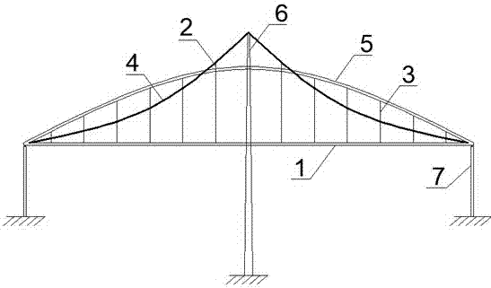
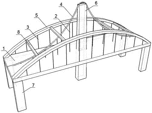
[0024] Example 1: see figure 1 , the structural system is a combination of a self-anchored suspension bridge with two towers and two cable planes and a single-arch-rib-arch-girder composite bridge. It consists of 6 towers, 7 side piers and 8 wind braces. The main girder 1 is a steel stiffened girder with a box-shaped cross-section. figure 1 Simplified as a rectangle. The bridge tower 6 is a square single-column concrete bridge tower with a variable cross-section, and the cross-section gradually increases from top to bottom, which conforms to the stress characteristics of the bridge tower. The bridge tower 6 is located in the middle of the main girder 1, ensuring that the main beam 1 on both sides of the bridge tower 6 has an equal span, and the intersection of the bridge tower 6 and the main beam 1 is not connected to the The main beam 1 is connected to make the main beam 1 fully float. The main cable 4 is supported by the pylon 6, and is erected above the middle of the ma...


PUM


Abstract

The invention relates to an equal-span self-anchored span wire-arched beam cooperative system bridge. The equal-span self-anchored span wire-arched beam cooperative system bridge comprises a main beam, a span-wire suspender, an arched suspender, a main cable, an arch rib, a bridge tower, abutment piers and a wind brace. The main cable and the arch rib are symmetrically arranged in the transverse direction of the bridge of the main beam, the span-wire suspender and the arched suspender which are distributed in the longitudinal direction of the bridge are connected to the main cable and the arch rib correspondingly, then the main beam is formed, and flexible support to the main beam is formed. The main cable crosses over the bridge tower, the two ends of the main cable are anchored at the end of the main beam, axial pressure is applied to the main beam, the arch rib is in rigid connection with the two ends of the main beam, the axial pressure is applied to the main beam, tension and compression are mutually balanced, and the abutment piers are supported at the two ends of the whole system. According to the equal-span self-anchored span wire-arched beam cooperative system bridge, an equal-span self-anchored suspension bridge pressing the main beam and an arch-beam composite bridge pulling the main beam are combined together, part of axial pressure in the main beam is counteracted, and the stability problem caused by overlarge axial pressure borne by the main beam when the span is large and the problems of overlarge section design and insufficient bearing capacity are solved. The structural system is reasonable in stress, the self-weight of the main beam is low, the span capacity is high, the anti-seismic and the wind-resistant performance is excellent, and the bridge is another one good structural form of large and middle span bridges.

Description

technical field [0001] The invention belongs to the technical fields of civil engineering and bridge engineering, and in particular relates to a suspension cable-arch cooperative system bridge, in particular to an equal-span self-anchored suspension cable-arch beam cooperative system bridge. Background technique [0002] In addition to providing spanning functions, bridges often become a symbolic landscape of a region with their unique shapes. Among many bridge structures, suspension bridges and arch bridges have the most beautiful curved shapes. Therefore, suspension bridges and arch bridges have become bridges of choice. A very competitive solution. [0003] The self-anchored suspension bridge in the suspension bridge is a special cable-bearing bridge type, which is different from the traditional ground-anchored suspension bridge. The system not only saves the cost of anchorage, but also relaxes the bridge type to the geological conditions of the bridge site, and is also ...

Claims


Application Information

Patent Timeline
IPC IPC(8): E01D12/00
Inventor 李涵袁万城党新志
Owner TONGJI UNIV
Why Eureka
Try Eureka