Auxiliary positioning device and positioning method of foundation bolts

An auxiliary positioning and anchor bolt technology, which is applied in the field of auxiliary positioning devices and anchor bolt positioning, can solve the construction restrictions of anchor bolt positioning, affect the radian deviation, force and stability of the upper steel structure, and measure tool data errors major issues

Active Publication Date: 2017-10-20
莱芜钢铁集团建筑安装工程有限公司
View PDF9 Cites 1 Cited by
  • Summary
  • Abstract
  • Description
  • Claims
  • Application Information

AI Technical Summary

Problems solved by technology

The commonly used anchor bolt installation method is the method of projecting points from the center point of the reinforced concrete foundation cap to the anchor bolt installation point to determine the anchor bolt installation position. Due to the distance between the ring foundation center point and the anchor bolt installation point Larger, so the error of the data measured by the measuring tool is also relatively large, and in the calibration process, the cumulative error of multiple measurements will also increase the positioning error of the installation position of the anchor bolts, which seriously affects the radian deviation of the upper steel structure , stress and stability, so that the construction quality cannot be guaranteed
[0004] In addition, for the normal implementation of the above positioning method, it is also necessary to ensure that the central point of the reinforced concrete foundation cap and the installation point of the external anchor bolts maintain a clear view (that is, there are no obstacles between the two points), so that the construction of the positioning of the anchor bolts will be greatly improved. come a big limit

Method used


Image

  • Auxiliary positioning device and positioning method of foundation bolts
  • Auxiliary positioning device and positioning method of foundation bolts
  • Auxiliary positioning device and positioning method of foundation bolts

Examples


Embodiment Construction

[0043]The invention provides an auxiliary positioning device. By using the auxiliary positioning device to locate the anchor bolts, the positioning accuracy of the anchor bolts can be significantly improved, and the construction quality is guaranteed.

[0044] The following will clearly and completely describe the technical solutions in the embodiments of the present invention with reference to the accompanying drawings in the embodiments of the present invention. Obviously, the described embodiments are only some, not all, embodiments of the present invention. Based on the embodiments of the present invention, all other embodiments obtained by persons of ordinary skill in the art without making creative efforts belong to the protection scope of the present invention.

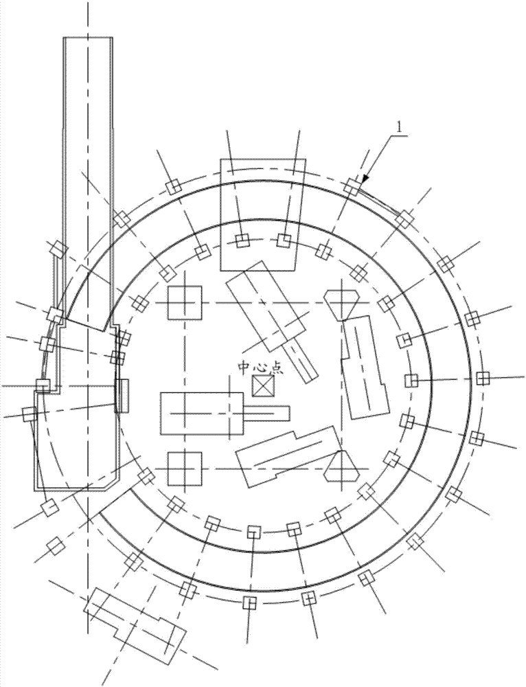
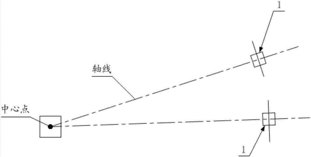
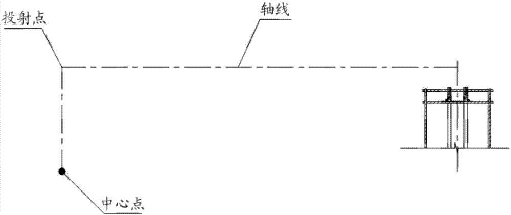
[0045] Such as Figure 1-Figure 9 As shown, the auxiliary positioning device provided by the embodiment of the present invention is used for circular arrangement (such as figure 1 When the anchor bolt 8 is set...


PUM


Abstract

The invention discloses an auxiliary positioning device. The device is used for positioning foundation bolts on a reinforced concrete foundation platform. The device comprises a vertical supporting rod, a first axis positioning rod arranged on the vertical supporting rod and a first radius positioning rod; the axis which is emergent from the radial direction of the center point of the ring defined by the foundation bolts can be crossed with the first axis positioning rod arranged in the tangent direction of the ring; the first radius positioning rod is arranged on the supporting rod or the first axis positioning rod and is arranged in the radial direction of the ring, the track of the ring can be crossed with the first radius positioning rod. When the foundation bolts are positioned through the auxiliary positioning device, the axis point and the radius point can be precisely positioned on the bolts, through the axis point and the radius point, the reference point is positioned, positioning of the mounting position of the foundation bolts can be achieved, in the process, due to the fact that the measuring distance between the axis point and the radius point and the reference point is obviously reduced, the measuring error is greatly reduced, positioning precision of the foundation bolts can be obviously improved, and the construction quality is ensured.

Description

technical field [0001] The present invention relates to the technical field of construction tools, in particular to an auxiliary positioning device for positioning anchor bolts, and also relates to an anchor bolt positioning method suitable for the above auxiliary positioning device. Background technique [0002] The anchor bolt is an indispensable fastening connector embedded in the reinforced concrete foundation to connect with the upper steel structure frame. , Fix the upper steel structure frame on the reinforced concrete foundation, so as to stabilize the upper steel structure, so that it will not be damaged by the influence of equipment operation and natural weather. [0003] At present, there are more and more applications of reinforced concrete foundation caps (that is, multiple concrete foundations in a circular arrangement, and anchor bolts need to be installed on each concrete foundation) in industrial buildings, such as sintered ring coolers, steel chimneys, etc....

Claims


Application Information

Patent Timeline
Patent Type & Authority Applications(China)
IPC IPC(8): E02D27/42E02D27/44
CPCE02D27/42E02D27/44
Inventor 许丽丽荆丹丹张丽媛徐志超
Owner 莱芜钢铁集团建筑安装工程有限公司
Why Eureka
Try Eureka