
Electronic evidence obtaining room based on multifunctional design

An electronic forensics, multi-functional technology, applied in special buildings, small buildings, building types, etc., can solve problems such as waiting for the rabbit, difficult to use the monitoring system effectively, unable to cover monitoring points, etc., and achieve timely improvement. performance and accuracy, saving the consumption of mains resources, reducing the effect of vibration damage

Inactive Publication Date: 2017-10-20
福建中锐电子科技有限公司
View PDF0 Cites 2 Cited by
  • Summary
  • Abstract
  • Description
  • Claims
  • Application Information

AI Technical Summary

Problems solved by technology

[0002] In order to prevent the occurrence of criminal pedestrians and stop the occurrence of criminal acts in a timely manner before criminal acts occur, monitoring suspects is a commonly used method at present. Most of the existing monitoring systems are fixed. Users rely on historical data or experience, and according to For monitoring requirements, pre-select monitoring points, and then set up a monitoring system at the pre-selected monitoring points. This type of monitoring system can only select one or several fixed points, and cannot cover all monitoring points. For example, in crowded places Set up a monitoring system, but it is basically not possible to set up a monitoring system in a sparsely populated and secluded place, and this type of monitoring system can basically only be in a state of waiting when responding to emergencies. If the place where the emergency occurs does not have monitoring coverage , it is difficult for the monitoring system to effectively use

Method used


Image

  • Electronic evidence obtaining room based on multifunctional design
  • Electronic evidence obtaining room based on multifunctional design

Examples


Embodiment Construction

[0013] The following will clearly and completely describe the technical solutions in the embodiments of the present invention with reference to the accompanying drawings in the embodiments of the present invention. Obviously, the described embodiments are only some, not all, embodiments of the present invention. Based on the embodiments of the present invention, all other embodiments obtained by persons of ordinary skill in the art without making creative efforts belong to the protection scope of the present invention.

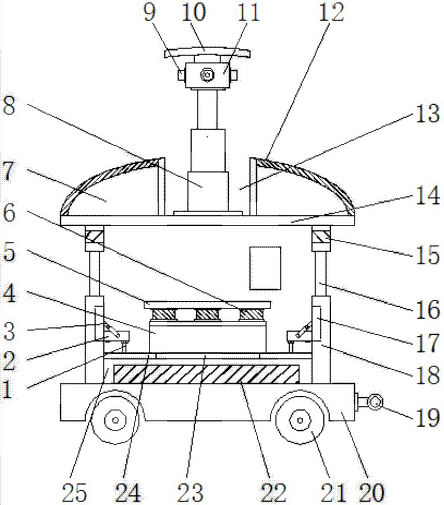
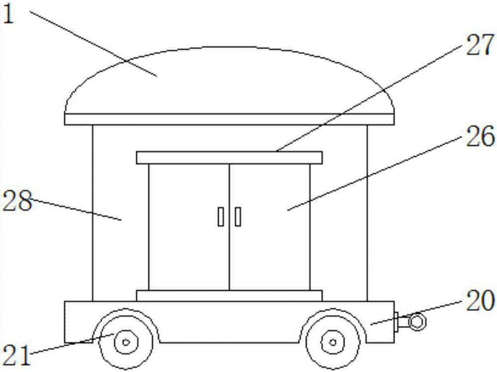
[0014] see Figure 1-2 , an embodiment provided by the present invention: an electronic evidence collection room based on multi-functional design, including a mobile support frame 20, a chamber body 18 and a ceiling 7, one end of the mobile support frame 20 is equipped with a traction ring 19 by a bolt, and the mobile support frame 20 Rollers 21 are installed on the bottom of the frame through the rotating shaft, which is convenient to move, realizes movable m...


PUM


Abstract

The invention discloses an electronic evidence collection room based on a multi-functional design, which comprises a mobile support frame, a room body and a ceiling. A room body is installed on the top of the mobile support frame. A workbench for obtaining evidence is provided, and accommodating chambers are provided on the inner walls of the chambers at both ends of the forensic collecting rack, and support plates are installed inside the accommodating chambers through rotating shafts, and observation windows are provided on the side walls of the upper chambers of the accommodating chambers , the top of the chamber body is fixed with a roof, a ceiling is provided above the roof, and a solar panel is installed on the upper surface of the ceiling, a cavity is provided in the middle of the ceiling, and an electric lifter is installed inside the cavity through bolts , and the output end of the electric lifter is fixedly connected with a mounting base, and infrared cameras are installed on the four sides of the mounting base. The present invention can also realize on-site monitoring and evidence collection while realizing electronic evidence collection, which greatly improves the timeliness and accuracy of evidence collection.

Description

technical field [0001] The invention relates to the technical field of electronic evidence collection, in particular to an electronic evidence collection room based on multifunctional design. Background technique [0002] In order to prevent the occurrence of criminal pedestrians and stop the occurrence of criminal acts in a timely manner before criminal acts occur, monitoring suspects is a commonly used method at present. Most of the existing monitoring systems are fixed. Users rely on historical data or experience, and according to For monitoring requirements, pre-select monitoring points, and then set up a monitoring system at the pre-selected monitoring points. This type of monitoring system can only select one or several fixed points, and cannot cover all monitoring points. For example, in crowded places Set up a monitoring system, but it is basically not possible to set up a monitoring system in a sparsely populated and secluded place, and this type of monitoring syste...

Claims


Application Information

Patent Timeline
Patent Type & Authority Applications(China)
IPC IPC(8): E04H1/12
CPCE04H1/1205
Inventor 郑友敏郑旭
Owner 福建中锐电子科技有限公司
Learn More