A Fixed Structure of Plate Potential Resistor

A fixed structure and potential technology, which is applied in the electrical component structure association, transformer/inductor parts, circuits, etc., can solve the problem of increasing the cost of the transformer due to the height of the potential resistance, and achieve the goal of reducing the height, reducing the amount, and reducing the manufacturing cost. Effect

Active Publication Date: 2019-06-11
CHINT ELECTRIC
View PDF3 Cites 0 Cited by
  • Summary
  • Abstract
  • Description
  • Claims
  • Application Information

AI Technical Summary

Problems solved by technology

[0003] The problem to be solved by the present invention is that the height of the existing potential resistance is too large to increase the cost of the transformer

Method used


Image

  • A Fixed Structure of Plate Potential Resistor
  • A Fixed Structure of Plate Potential Resistor

Examples


Embodiment

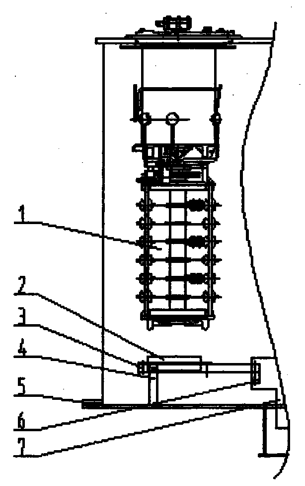
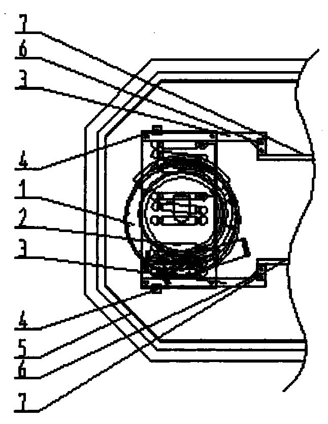
[0013] As shown in claim 1, it is a fixed structure of a plate-type potentiometer provided by the present invention. The potential resistor 2 is installed on the bottom 5 of the fuel tank, and an on-load switch 1 is installed above the potential resistor 2 in the fuel tank. The two sides of the potential resistor 2 The side is symmetrically provided with lower clamps 7, which are respectively high-voltage lower clamps and low-pressure lower clamps. A fixed plate 6 is symmetrically welded to the center lines of the high-pressure lower clamps and low-pressure lower clamps; the fixed plate 6 is symmetrical Install an L-shaped electrical laminated wood piece 1, and fasten it with blackened bolts, nuts and washers; the potential resistor 2 is placed on the two electrical laminated wood pieces 1 3, and fastened with insulating screws and nuts (the installation hole that matches with potential resistance 2 is arranged on the electrical laminated wood piece-3); Between the electrician ...


PUM


Abstract

The invention discloses a fixing structure of a plate-type potential resistor. The fixing structure includes a potential resistor positioned under an on-load switch; the potential resistor is fixed on a bottom of an oil tank; a high-voltage lower clamping member and a low-voltage lower clamping member are symmetrically arranged on two sides of the potential resistor; fixing plates are arranged on the high-voltage lower clamping member and the low-voltage lower clamping member; first wireman lamination wood members are arranged on the fixing plates; and the potential resistor are fixedly connected to the two first wireman lamination wood members. Independent installation of the plate-type potential resistor can be achieved, the height of the on-load switch is lowered, the height of a transformer oil tank is lowered, the use amount of steel plates and transformer oil is reduced, and the manufacturing cost of a transformer is greatly reduced.

Description

technical field [0001] The invention relates to a support structure of an oil-immersed transformer on-load switch plate type potential resistance, belonging to the technical field of electric equipment. Background technique [0002] For the on-load tap changer, the voltage adjustment function is realized without cutting off the load. In the mode of forward and reverse voltage regulation and coarse and fine voltage regulation, during the operation of the change-over selector of the tap changer, because the voltage regulation winding is temporarily separated from the winding, the potential of the tap winding is suspended. If the floating potential is too high, it will discharge, causing the transformer oil to decompose and generate gas, which will endanger the insulation performance of the product. To solve the above hazards, it is necessary to use the method of connecting potential resistance. The traditional potentiometer is installed at the bottom of the on-load switch and...

Claims


Application Information

Patent Timeline
Patent Type & Authority Patents(China)
IPC IPC(8): H01F27/40H01F29/04
CPCH01F27/402H01F29/04H01F2027/404
Inventor 王旭东单良邓海生
Owner CHINT ELECTRIC
Why Eureka
Try Eureka