
Photoelectric separation connection device

A technology for photoelectric separation and connection devices, which is applied to the parts, connections, and coupling devices of connection devices, which can solve problems such as poor sealing and achieve the effect of reducing assembly

Active Publication Date: 2021-08-27
PETROCHINA CO LTD
View PDF0 Cites 0 Cited by
  • Summary
  • Abstract
  • Description
  • Claims
  • Application Information

AI Technical Summary

Problems solved by technology

[0003] The main purpose of the present invention is to provide a photoelectric separation connection device to solve the problem of poor sealing of the photoelectric separation connection device in the prior art

Method used


Image

  • Photoelectric separation connection device
  • Photoelectric separation connection device
  • Photoelectric separation connection device

Examples


Embodiment Construction

[0026] It should be noted that, in the case of no conflict, the embodiments in the present application and the features in the embodiments can be combined with each other. The present invention will be described in detail below with reference to the accompanying drawings and examples.

[0027] It should be noted that, unless otherwise specified, all technical and scientific terms used in this application have the same meaning as commonly understood by those of ordinary skill in the art to which this application belongs.

[0028] In the present invention, unless stated otherwise, the used orientation words such as "upper, lower, top, bottom" are usually for the directions shown in the drawings, or for the parts themselves in the vertical, In terms of vertical or gravitational direction; similarly, for the convenience of understanding and description, "inner and outer" refer to the inner and outer relative to the outline of each component itself, but the above orientation words ...


PUM


Abstract

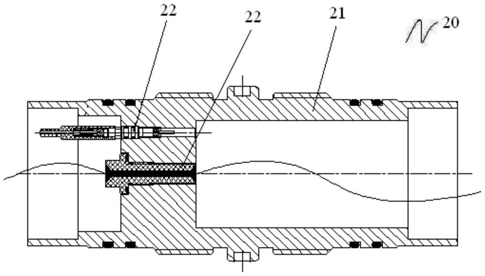
The invention provides a photoelectric separation connection device, comprising: a plurality of joint assemblies, each joint assembly has a photoelectric separation part and a plurality of adapters, the adapters are fixedly arranged, and the photoelectric separation part separates the cable and the optical fiber of the photoelectric composite cable , the separated cables and optical fibers are connected with the adapter; the connection assembly, each joint assembly is connected through the connection assembly, and together with the connection assembly forms a sealed cavity, the adapters of different joint assemblies pass through the sealed cavity The connection lines are connected in one-to-one correspondence. The invention solves the problem of poor sealing of the photoelectric separation connection device in the prior art.

Description

technical field [0001] The invention relates to the technical field of petroleum well logging, in particular to a photoelectric separation and connection device. Background technique [0002] At present, fiber optic micro-seismic detectors and fiber-optic micro-seismic monitoring technologies have been widely used abroad, not only for guiding the fracturing process in many places, but also for real-time geophysical monitoring and well completion processes. During the use of the above-mentioned instruments, it is often necessary to connect and seal the cables and optical fibers in the photoelectric composite cable with the cables and optical fibers in the downhole photoelectric collection nipple respectively, but there is no corresponding device in the prior art, and With the traditional connecting device, the sealing of the connection is poor, and the oil and gas in the well will affect the monitoring data obtained by the optical fiber and cable, resulting in the problem of ...

Claims


Application Information

Patent Timeline
Patent Type & Authority Patents(China)
IPC IPC(8): H01R31/06H01R13/52H01R13/502H01R13/56H01R13/72G02B6/38E21B47/12
CPCE21B47/12G02B6/38H01R13/502H01R13/5202H01R13/521H01R13/56H01R13/72H01R31/06
Inventor 谢斌潘勇芦志伟段胜男王宁博胡承军孙新姬小娟汪志楚恒智
Owner PETROCHINA CO LTD
Learn More