
Railway vehicle end structure for tight-lock coupler and end traction and railway vehicle

A rail vehicle and end structure technology, which is applied in the field of rail vehicles, can solve the installation and operation requirements, and can not meet the problems of close-connected coupler buffer devices, etc., so as to solve the shortage of installation space, improve vehicle dynamic performance, and reduce longitudinal impact force effect

Active Publication Date: 2022-08-05
ZHUZHOU ELECTRIC LOCOMOTIVE CO
View PDF7 Cites 0 Cited by
  • Summary
  • Abstract
  • Description
  • Claims
  • Application Information

AI Technical Summary

Problems solved by technology

[0007] The technical problem to be solved by the present invention is that the end structure of the existing rail vehicles cannot meet the installation and operation requirements of the close-connected coupler buffer device, and also meet the requirements of the end traction mode between the car body and the bogie. The present invention provides a A rail vehicle end structure and rail vehicle that can not only meet the requirements for the installation and operation of the close-connected coupler buffer device, but also meet the requirements for transmission of traction force and braking force between the car body and the bogie by means of end traction.

Method used


Image

  • Railway vehicle end structure for tight-lock coupler and end traction and railway vehicle
  • Railway vehicle end structure for tight-lock coupler and end traction and railway vehicle
  • Railway vehicle end structure for tight-lock coupler and end traction and railway vehicle

Examples


Embodiment Construction

[0035] The present invention is further described below with reference to specific preferred embodiments, but the protection scope of the present invention is not limited thereby.

[0036] For ease of description, the relative positional relationship of each component, such as: top, bottom, left, right, etc., is described according to the layout direction of the drawings in the specification, and does not limit the structure of this patent.

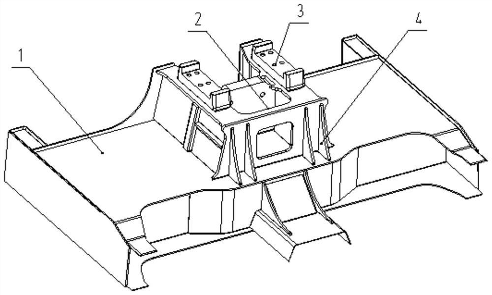
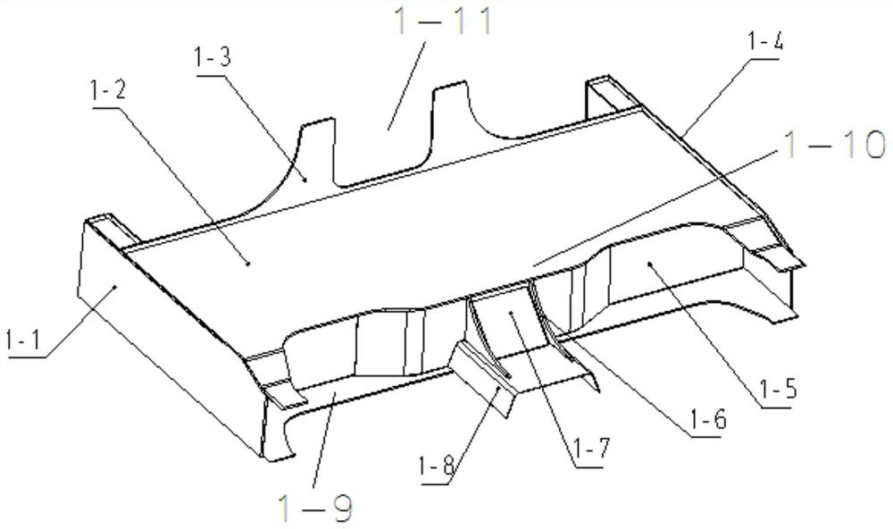
[0037] like figure 1As shown, an embodiment of the rail vehicle end structure for close coupling and end traction of the present invention includes a main bearing structure 1 at the end of the car body, a coupler box 2, a traction device mounting seat 3, and a transition rib 4.

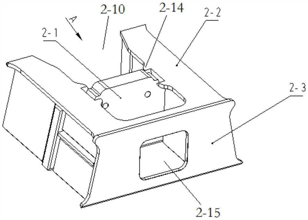
[0038] The coupler box 2 is located under the main bearing structure 1 at the end of the vehicle body, the traction device mounting seat 3 is located directly under the coupler box 2, and the transition rib plate 4 is located on the back of the rear end plate of ...


PUM


Abstract

The invention discloses a railway vehicle end structure for tight-lock couplers and end traction and a railway vehicle, the railway vehicle end structure comprises a vehicle body end main bearing structure (1), a coupler box (2) and a traction device mounting seat (3), and the coupler box (2) and the traction device mounting seat (3) are sequentially mounted below the vehicle body end main bearing structure; and the traction device mounting seat is positioned right below the coupler box. The installation and application requirements of the tight-lock coupler buffer device can be met, meanwhile, the requirement that traction force and braking force are transmitted between a vehicle body and a bogie in an end traction mode can be met, the structure is simple, the occupied space for installation is small, and cost is low. The problem that the installation space is limited when the tight-lock coupler and the end traction are used together is effectively solved.

Description

technical field [0001] The invention relates to a rail vehicle, in particular to a rail vehicle end structure and a rail vehicle for a close-contact coupler and an end pulling. Background technique [0002] At present, traditional mechanical couplers are mainly used for the connection between vehicles on rail rolling stock. Due to the large longitudinal gap between the two trailer couplers, a large longitudinal impulse will be generated during the operation of the vehicle, which will affect the vehicles, especially the passenger transport. The comfort of the occupants in the vehicle. Therefore, in order to reduce the coupling gap between vehicles, minimize the longitudinal impact force of the vehicle, and improve the comfort of the vehicle, the close coupling coupler with a small coupling gap is gradually widely used on passenger vehicles. [0003] However, the close-contact couplers are mostly used in subway vehicles, power-dispersed EMUs and high-speed trains. Compared wi...

Claims


Application Information

Patent Timeline
Patent Type & Authority Applications(China)
IPC IPC(8): B61G7/10B61G9/20
CPCB61G7/10B61G9/20Y02T30/00
Inventor 金希红童小山何永强李祥涛曹媛曾燕军李明明李龙刘宏也温坤陆军梁培阳
Owner ZHUZHOU ELECTRIC LOCOMOTIVE CO
Learn More