
Method for stamping washers

A technology of gaskets and stamping heads, which is applied in the field of parts processing, can solve the problems of increasing the processing cost of internal tooth lock washers and reducing the processing efficiency of internal tooth lock washers, so as to reduce the stamping defective rate, fast transmission, and simplify the calibration steps Effect

Active Publication Date: 2017-10-24
YANCHENG TONGJI AUTO PARTS CO LTD
View PDF8 Cites 4 Cited by
  • Summary
  • Abstract
  • Description
  • Claims
  • Application Information

AI Technical Summary

Problems solved by technology

[0003] The stamping process of the internal tooth lock washer includes two processes. First, the sheet blank is stamped into a blank with the prototype of the internal tooth lock washer, and then the stamping part on the blank is stamped. When stamping the inner tooth lock washer, the stamping head is located on the upper surface of the stamping part of the internal tooth lock washer, and at the same time, the ejector rod needs to be in contact with the lower surface of the stamping part of the internal tooth lock washer, and then the stamping head is pressed against the stamping part of the internal tooth lock washer For stamping, when the internal tooth lock washer is directly placed on the ejector pin, it is difficult for the stamping part to face the stamping part of the internal tooth lock washer; Misalignment will lead to the production of defective internal tooth lock washers, which will greatly reduce the processing efficiency of internal tooth lock washers and increase the processing cost of internal tooth lock washers

Method used


Image

  • Method for stamping washers
  • Method for stamping washers
  • Method for stamping washers

Examples


Embodiment Construction

[0023] The present invention will be described in further detail below by means of specific embodiments:

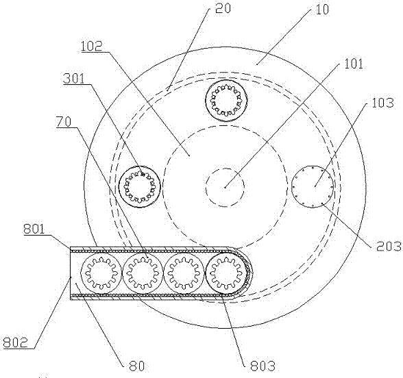
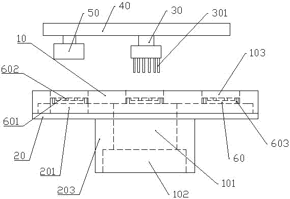
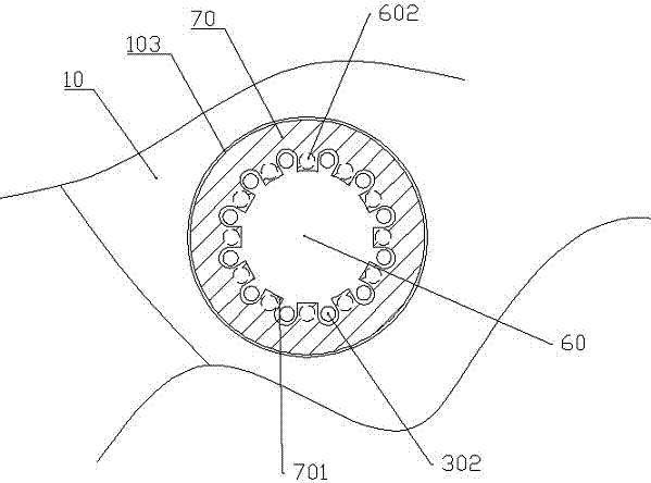
[0024] The reference signs in the accompanying drawings of the description include: turntable 10, rotating shaft 101, motor 102, processing through groove 103, fixed table 20, support block 201, spring 202, unloading rod 203, installation sleeve 204, support column 205, telescopic rod 30. Driving lever 301, laser generator 302, laser receiver 303, frame 40, stamping head 50, support table 60, groove 601, ejector rod 602, unloading hole 603, internal tooth lock washer 70, stamping part 701, transfer box 80, ball 801, feed inlet 802, discharge outlet 803,.

[0025] The stamping device in the embodiment is basically as attached figure 1 And attached figure 2 As shown: it includes a turntable 10 , a vertically arranged rotating shaft 101 , a motor 102 , a supporting mechanism, a calibration stamping mechanism and a transfer box 80 .

[0026]The turntable 10 is horizontall...


PUM


Abstract

The invention relates to the field of part processing, and in particular discloses a method for stamping washers. When internal teeth lock washers are stamped, machining through grooves on a turntable are rotating, so that four steps, namely feeding, calibration, stamping and pick-up, are conducted on the internal teeth lock washers in the four machining through grooves in sequence so as to achieve cycle machining of the internal teeth lock washers and improve the stamping efficiency of the internal teeth lock washers; meanwhile, before the internal teeth lock washers are stamped, the positions of the internal teeth lock washers can be calibrated through a calibration stamping mechanism so as to ensure that stamping parts of the internal teeth lock washers can be accurately stamped, and the stamping defective rate of the internal teeth lock washers is reduced. According to the method for stamping washers, the internal teeth lock washers can be aligned with a stamping head and a kicker pin, so that the stamping efficiency of the internal teeth lock washers is improved.

Description

technical field [0001] The invention belongs to the field of part processing, and in particular relates to a stamping method of a washer. Background technique [0002] The internal tooth lock washer is a flat thin-walled part, which can be used between the nut and the bolt, which can effectively prevent the spring and the bolt from loosening. At the same time, the internal tooth lock washer is smaller than the ordinary spring washer, and the fastener is evenly stressed. , It is also reliable to prevent loosening; at the same time, the internal tooth lock washer is also a simple locking retaining ring, which can be used on the shaft. At this time, the teeth on the inner side of the washer have the function of preventing retreat. [0003] The stamping process of the internal tooth lock washer includes two processes. First, the sheet blank is stamped into a blank with the prototype of the internal tooth lock washer, and then the stamping part on the blank is stamped. When stam...

Claims


Application Information

Patent Timeline
Patent Type & Authority Applications(China)
IPC IPC(8): B21D22/08B21D53/20B21C51/00
CPCB21C51/00B21D22/08B21D53/20
Inventor 陈明友
Owner YANCHENG TONGJI AUTO PARTS CO LTD
Learn More