Adjustable type wire cutting machining roller

A wire cutting and adjustable technology, applied in electric processing equipment, metal processing equipment, manufacturing tools, etc., can solve the problems of increasing installation and adjustment steps, inconvenient promotion and use, and increasing production costs, so as to improve accuracy and increase thickness. , the effect of reducing wear

Inactive Publication Date: 2017-10-24
绍兴市上虞舜东橡塑制品有限公司
View PDF5 Cites 5 Cited by
  • Summary
  • Abstract
  • Description
  • Claims
  • Application Information

AI Technical Summary

Problems solved by technology

The above technical solution can realize slicing and grooving of the workpiece, but the groove on the multi-groove guide wheel of this technical solution is a fixed groove, which can only process slices with a fixed width, and the scope of application is small. When the cutting width of the workpiece needs to be adjusted, it needs to be replaced. The multi-groove guide wheel with the corresponding line groove width increases the steps of installation and adjustment, and the production of multi-groove guide wheels of different specifications also increases the production cost of the device, which is not easy to promote and use

Method used


Image

  • Adjustable type wire cutting machining roller
  • Adjustable type wire cutting machining roller
  • Adjustable type wire cutting machining roller

Examples


Embodiment approach

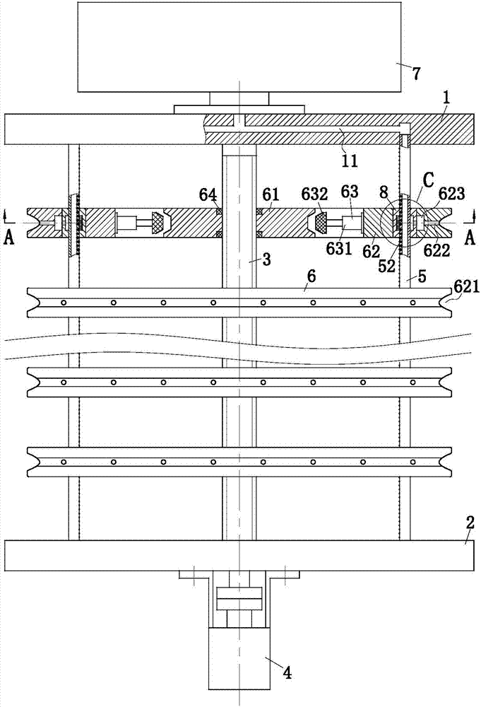
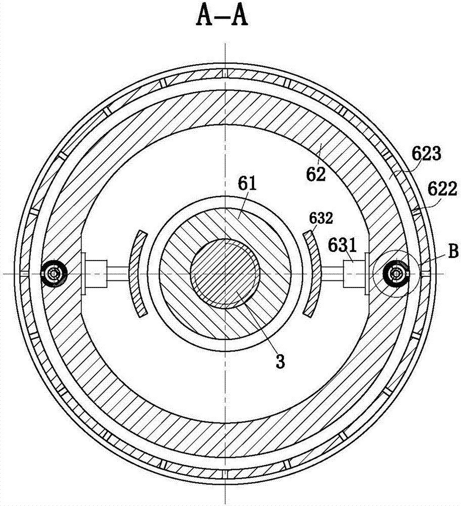
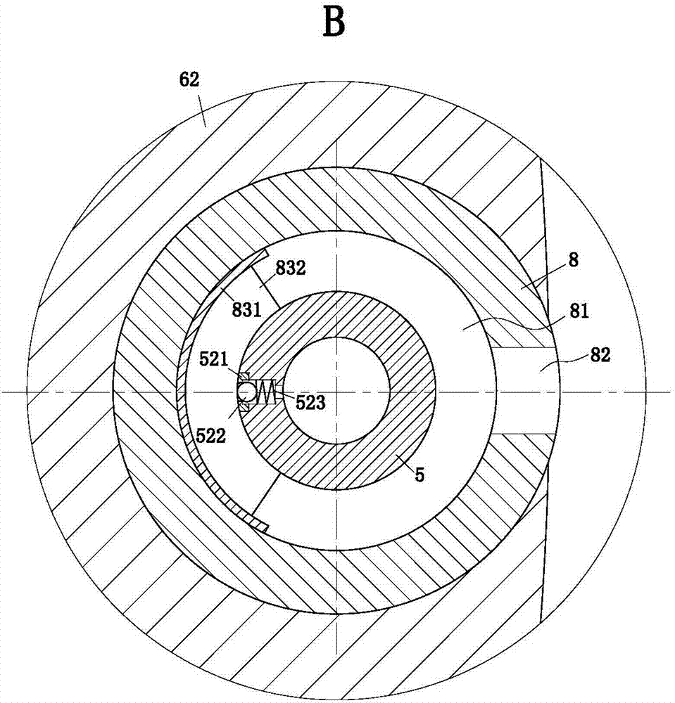
[0031] As an embodiment of the present invention, the guide rod 5 is a hollow rod, and the guide rod 5 is equidistantly provided with a plurality of water outlet holes 51 along its own length direction, and a pressing module 52 is installed in the water outlet hole 51, and the pressing module 52 is used for Discharge the coolant located in the guide rod 5. When the press module 52 is pressed, the coolant will be discharged from the water outlet hole 51. When the press module 52 is not pressed, the press module 52 will block the water outlet hole 51, and the coolant will be will not flow out; the fixed plate 1 is provided with a cooling channel 11, and the cooling channel 11 introduces the cooling liquid from the center of the fixed plate 1 into the guide rod 5; the bottom of the guide groove 621 of the guide wheel 62 is provided with a plurality of Cooling holes 622, a plurality of cooling holes 622 are evenly arranged along the circumferential direction of the guide wheel 62, ...


PUM


Abstract

The invention belongs to the field of wire cutting and particularly relates to an adjustable type wire cutting machining roller. The adjustable type wire cutting machining roller comprises a fixing plate, a mounting plate, a threaded rod, a servo motor, guide rods, guiding assemblies and a controller. The fixing plate is coaxially mounted on an output shaft of a reduction box. The threaded rod is coaxially mounted between the fixing plate and the mounting plate in a rotatable manner through a bearing. The servo motor is fixed to the mounting plate and drives the threaded rod to rotate through a coupling. The guide rods are arranged to be parallel with the threaded rod and mounted between the fixing plate and the mounting plate. The guiding assemblies are mounted on the threaded rod and the guide rods in an equally-spaced manner. Each guiding assembly comprises moving nuts, guiding wheels and connecting components. Each moving nut is mounted on the threaded rod and is in threaded fit with the threaded rod. Each guiding wheel is mounted on the corresponding guide rod and arranged to be coaxial with the threaded rod. The guiding wheels can slide along the guide rods. Each connecting component is mounted on the corresponding guiding wheel and used for connecting the corresponding guiding wheel with the corresponding moving nut. By means of the adjustable type wire cutting machining roller, distances of wires subjected to wire cutting can be adjusted automatically, and the application scope of a wire cutting machine is widened.

Description

technical field [0001] The invention belongs to the field of wire cutting, in particular to an adjustable wire cutting processing roller. Background technique [0002] Slicing is an important step in the processing of LED substrates, solar silicon wafers, etc. The most widely used in the slicing link is the multi-wire cutting machine (wire saw). The processing principle is that the high-speed moving steel wire drives the silicon carbide abrasive particles scattered in the working fluid to move, and the moving abrasive particles rub against the surface of the workpiece, thereby realizing the slice processing of the workpiece. In essence, multi-wire cutting machine processing is a kind of grinding processing. The surface of the processed slices has line marks and the depth of the damaged layer is deep. In the case of harder materials, wire breakage is very serious, and the cost of multi-wire cutting machines is very high. Compared with the multi-wire cutting machine, the WE...

Claims


Application Information

Patent Timeline
Patent Type & Authority Applications(China)
IPC IPC(8): B23H7/02B23H7/10B23H11/00
CPCB23H7/02B23H7/10B23H7/105B23H11/00
Inventor 陈壮壮胡敏李超王涛
Owner 绍兴市上虞舜东橡塑制品有限公司
Why Eureka
Try Eureka