
Light guide arm used for laser shock wave technology

A technology of shock wave and light guide arm, applied in the field of light guide arm, can solve the problems of poor flexibility and low efficiency, achieve the effect of convenient installation and disassembly, and improve work efficiency

Inactive Publication Date: 2017-10-24
WENZHOU UNIVERSITY
View PDF9 Cites 2 Cited by
  • Summary
  • Abstract
  • Description
  • Claims
  • Application Information

AI Technical Summary

Problems solved by technology

[0003] The purpose of the present invention is to overcome the deficiencies in the prior art and provide a light guide arm for laser shock wave technology, aiming to solve the problems of poor flexibility and low efficiency due to the characteristics of shock waves that can only be transmitted by lens groups

Method used


Image

  • Light guide arm used for laser shock wave technology
  • Light guide arm used for laser shock wave technology
  • Light guide arm used for laser shock wave technology

Examples


Embodiment Construction

[0031] In order to have a clearer understanding of the technical features, purposes and effects of the present invention, specific implementations are now described in detail.

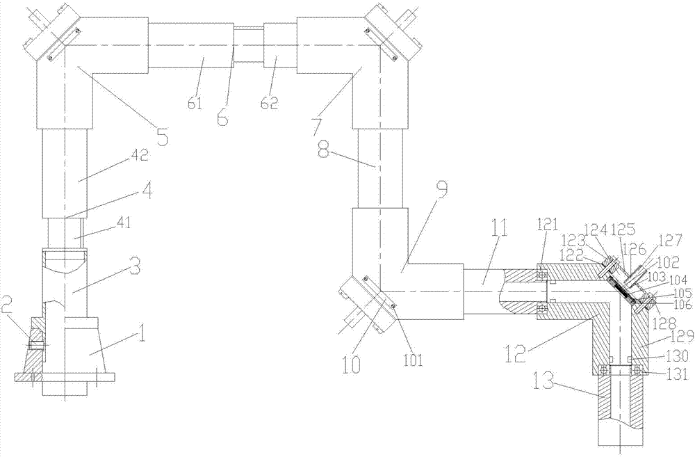
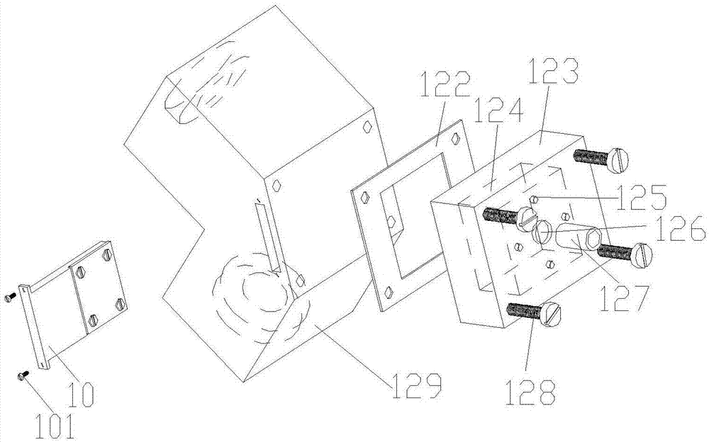
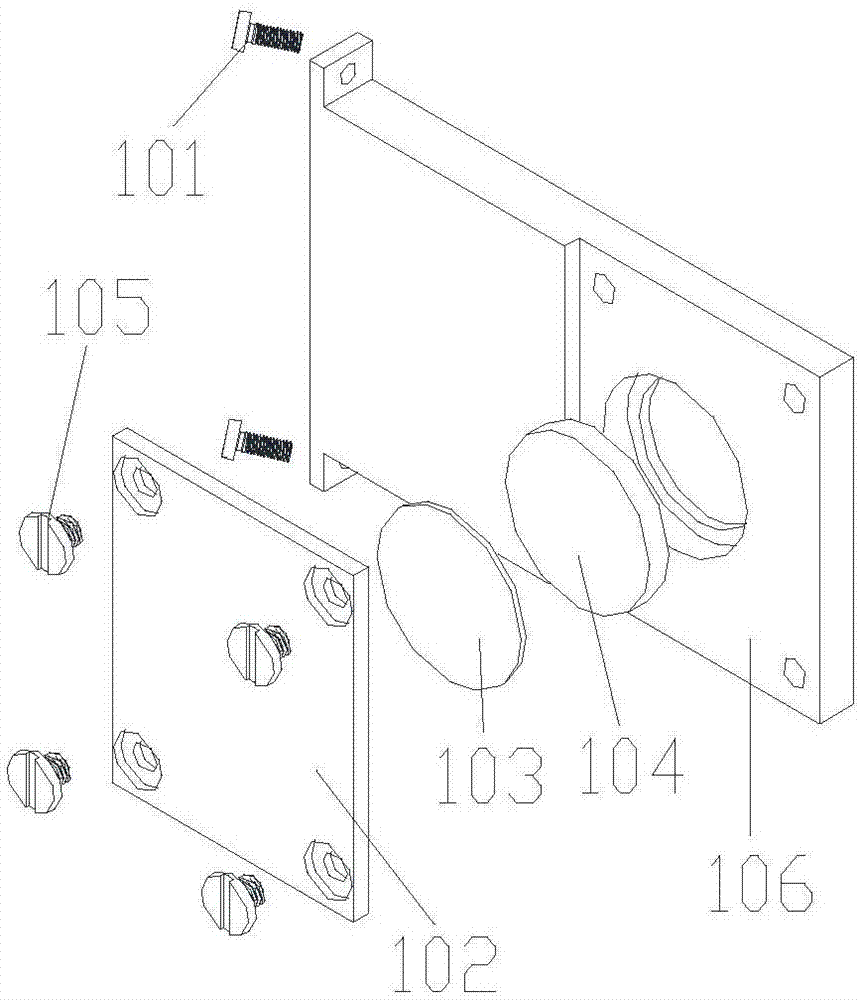
[0032] Such as Figure 1~3 As shown, the light guide arm for laser shock wave technology, including:

[0033] Base 1 for receiving laser light, connected with external equipment;

[0034] The base connecting pipe 3 for transmitting the optical path is fixedly connected with the base 1 through the fastening screw 2, and is fixedly connected with the longitudinal first telescopic pipe 41 of the longitudinal telescopic pipe 4 for increasing the processing range;

[0035] The first articulated arm 5 used for laser transmission is fixedly connected to the second longitudinal telescopic tube 42 of the longitudinal telescopic tube 4 through the first bearing, and is fixedly connected to the first horizontal telescopic tube 61 of the horizontal telescopic tube 6 through the second bearing;

[0036] The secon...


PUM


Abstract

The invention discloses a light guide arm used for a laser shock wave technology. The light guide arm comprises a base used for receiving lasers, a base connecting pipe used for transmitting a light path, a first joint arm used for laser transmission, a second joint arm used for the laser transmission, a third joint arm used for the laser transmission and a fourth joint arm used for the laser transmission; the base connecting pipe is fixedly connected with the base, and is fixedly connected with a longitudinal telescopic pipe; the first joint arm is connected with the longitudinal telescopic pipe, and is connected with a transverse telescopic pipe; the second joint arm is connected with the transverse telescopic pipe, and is fixedly connected with a first light guide pipe; the third joint arm is fixedly connected with the first light guide pipe, and is fixedly connected with a second light guide pipe; the four joint arm is fixedly connected with the second light guide pipe, and is fixedly connected with a light emerging pipe. The adjustment on the light path in any position point of a space and at any light beam angle is achieved, heat dissipation of glass is achieved, a card plug-in type glass base makes the glass more conveniently installed and dismounted, transmission of high-power shock waves in any position point of a space and any light beam angle is achieved, and the requirement of shock reinforcing engineering is met.

Description

technical field [0001] The invention relates to a light guide arm used in laser shock wave technology, and belongs to the technical field of marking equipment. Background technique [0002] At present, in the field of laser processing, due to the characteristics of laser shock waves, high power and short pulses will damage optical fibers and cannot be transmitted through optical fibers, so they must be transmitted through lenses. The existing laser shock wave technology uses mirror reflection, and its movement is not flexible enough. , the adjustment of the lens is complicated, and once the lens is polluted or the position of the optical element moves, the optical path of the entire laser light speed will be shifted, affecting the processing quality, and in severe cases, it will cause production accidents. The energy of the shock wave is too large and the lens is easily polluted by impurities in the airflow and the splash particles in the processing area are bonded, which wi...

Claims


Application Information

Patent Timeline
Patent Type & Authority Applications(China)
IPC IPC(8): B23K26/356B23K26/06
CPCB23K26/356B23K26/06
Inventor 冯爱新陈欢贾天代刘勇赵莹杨海华程好
Owner WENZHOU UNIVERSITY
Learn More