Glass feeding and discharging device for glass edge grinding machine

A glass edging and edging machine technology, which is applied to machine tools suitable for grinding workpiece edges, parts of grinding machine tools, grinding machines, etc., can solve problems affecting production efficiency and difficult handling, and achieve simple structure and easy promotion And the effect of novelty in use and design

Inactive Publication Date: 2017-10-24
BENGBU GAODE MACHINERY AUTOMATION SCI & TECH
View PDF0 Cites 2 Cited by
  • Summary
  • Abstract
  • Description
  • Claims
  • Application Information

AI Technical Summary

Problems solved by technology

[0003] After the actual pre-processing of the glass, because the corners of the glass have a lot of burrs and frizz, after the actual processing, the corners should be treated, especially the burrs on the corners should be uniformly polished to achieve the smoothness of the corners of the glass And there is no burr, but the glass edging machine is a relatively fixed mechanism, and the glass after initial processing is usually placed on a glass rack. The placed glass is divided into pieces and put into the edge grinding machine. Due to the necessity of processing, it must be carried by manpower when working here, which will not only cause actual transportation difficulties, but also affect the actual production efficiency.

Method used


Image

  • Glass feeding and discharging device for glass edge grinding machine
  • Glass feeding and discharging device for glass edge grinding machine

Examples


Embodiment 1

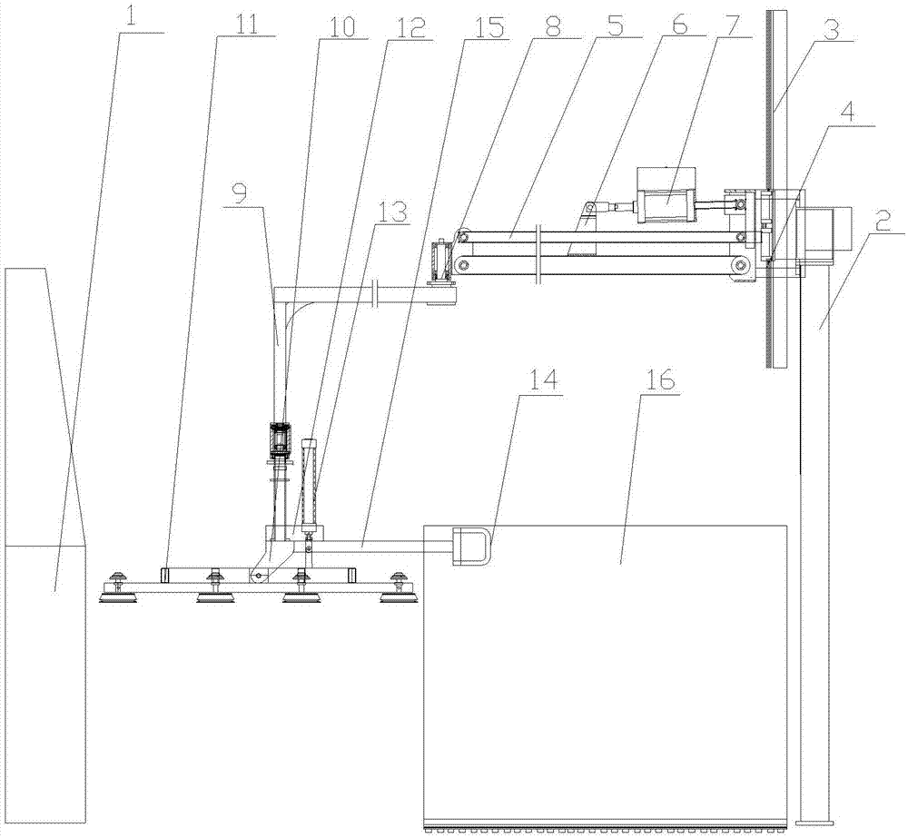
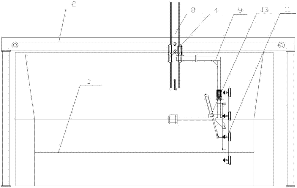
[0018] Such as figure 1 , figure 2 As shown, a glass loading and unloading device for glass edging machine, the front end of the glass edging machine 1, the main body is a gantry 2, and the vertical guide rail 3 that is arranged on the top of the gantry 2 and can move laterally A ferrule 4 that can move up and down on the vertical guide rail 3 is installed on the vertical guide rail 3. A crossbeam 5 that is movably connected with the ferrule 4 is installed on the ferrule 4. The top of the ferrule 4 and the middle part of the crossbeam 5 are all provided with Ear plates 6, and a jacking cylinder 7 is movably connected between the two ear plates 6, a shaft 8 is installed at the end of the beam 5, and an angular shaft 9 that can rotate around the shaft 8 is set on the supporting shaft 8, and the bottom of the angular shaft 9 is Connected with an angled plate 10, a glass suction cup 11 is installed on the angled plate 10, a positioning plate 12 is arranged between the angled pla...

Embodiment 2

[0020] Such as figure 1 , figure 2 As shown, a glass loading and unloading device for glass edging machine, the front end of the glass edging machine 1, the main body is a gantry 2, and the vertical guide rail 3 that is arranged on the top of the gantry 2 and can move laterally A ferrule 4 that can move up and down on the vertical guide rail 3 is installed on the vertical guide rail 3. A crossbeam 5 that is movably connected with the ferrule 4 is installed on the ferrule 4. The top of the ferrule 4 and the middle part of the crossbeam 5 are all provided with Ear plates 6, and a jacking cylinder 7 is movably connected between the two ear plates 6, a shaft 8 is installed at the end of the beam 5, and an angular shaft 9 that can rotate around the shaft 8 is set on the supporting shaft 8, and the bottom of the angular shaft 9 is Connected with an angled plate 10, a glass suction cup 11 is installed on the angled plate 10, a positioning plate 12 is arranged between the angled pla...


PUM


Abstract

A glass loading and unloading device for a glass edging machine. The main body is a gantry frame at the front end of the glass edging machine. It is arranged on the top of the gantry frame and can move horizontally. The vertical guide rail is installed on the vertical guide rail. There is a ferrule that can move up and down on the vertical guide rail, and a beam that is movably connected to the ferrule is installed on the ferrule. The top of the ferrule and the middle of the beam are provided with lugs, and there is a lift between the two lugs. Cylinder, a support shaft is installed at the end of the beam, an angle shaft that can rotate around the support shaft is set on the support shaft, an angle plate is connected to the bottom of the angle shaft, a glass suction cup is installed on the angle plate, and a positioning is arranged between the angle plate and the angle shaft The positioning plate is inverted and movably provided with a direction changing cylinder whose telescopic rod passes through the positioning plate and is connected to the glass suction cup. The present invention has a simple structure, and can realize the step-by-step movement of the glass panel through the mutual rotation and movement cooperation of a plurality of groups of movable shaft bodies, and the operation is convenient.

Description

technical field [0001] The invention relates to the field of manufacturing glass handling devices, in particular to a glass loading and unloading device for a glass edging machine. Background technique [0002] In people's daily life, whether it is an old building or a newly developed building, the innovation requirements for glass are very urgent. Glass is divided into two types: see-through and non-see-through. Flat glass is made by mechanically using grinding wheels to grind the surface into a uniform sand surface. Due to the rough surface, the light is diffusely reflected, and the light is transparent but not see-through. It can make the indoor light soft and not glaring. It is often used in bathrooms, toilets, office doors, windows and partitions that need to be concealed. [0003] After the actual pre-processing of the glass, because the corners of the glass have a lot of burrs and frizz, after the actual processing, the corners should be treated, especially the burrs...

Claims


Application Information

Patent Timeline
Patent Type & Authority Applications(China)
IPC IPC(8): B24B41/00B24B9/08B24B41/06
CPCB24B41/005B24B9/08B24B41/06
Inventor 余新圣陈培坤肖爱恩余金虎
Owner BENGBU GAODE MACHINERY AUTOMATION SCI & TECH
Why Eureka
Try Eureka