Rotating connector used for conveying two-phase flow containing solid abrasives

A rotary joint, phase flow technology, applied in grinding/polishing equipment, etc., can solve the problems of easy accumulation of abrasive particles and blockage of pipelines, low service life of rotary joints, limited working time and efficiency, etc., so as to avoid wear and sticking phenomenon. , to ensure flow stability and safety, service life and high work efficiency

Active Publication Date: 2017-10-24
CHINA RAILWAY CONSTR HEAVY IND
View PDF14 Cites 3 Cited by
  • Summary
  • Abstract
  • Description
  • Claims
  • Application Information

AI Technical Summary

Problems solved by technology

However, during the excavation process, the abrasive two-phase flow is continuously consumed. At this time, it needs to be replenished in time behind the roadheader. When conveying the abrasive, it is necessary to use a rotary joint to connect to the nozzle for transportation. The abrasive particles will enter the rotary joint under the pressure of the conveying medium. The gap between the inner shaft and the outer casing causes serious wear and stagnation. After working for a period of time, it needs to be shut down for maintenance and replacement, which limits the overall working time and efficiency, and seriously restricts the application and development of abrasive water jet technology in the field of tunnel excavation.
At the same time, due to the inertia of the solid abrasive particles, it is difficult to change the solid abrasive particles in time when the flow direction changes sharply, which makes the impact wear prone to occur at the flow direction change of the rotary joint, and the abrasive particles are also easy to accumulate and block the pipeline, resulting in a low service life of the rotary joint , high replacement rate

Method used


Image

  • Rotating connector used for conveying two-phase flow containing solid abrasives
  • Rotating connector used for conveying two-phase flow containing solid abrasives
  • Rotating connector used for conveying two-phase flow containing solid abrasives

Examples


Embodiment Construction

[0026] The present invention will be described in further detail below in conjunction with the accompanying drawings and specific embodiments, but the protection scope of the present invention is not limited thereby.

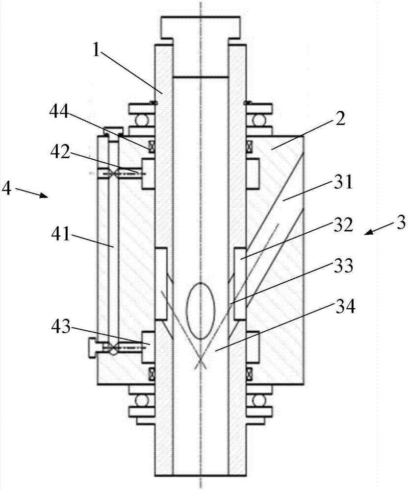
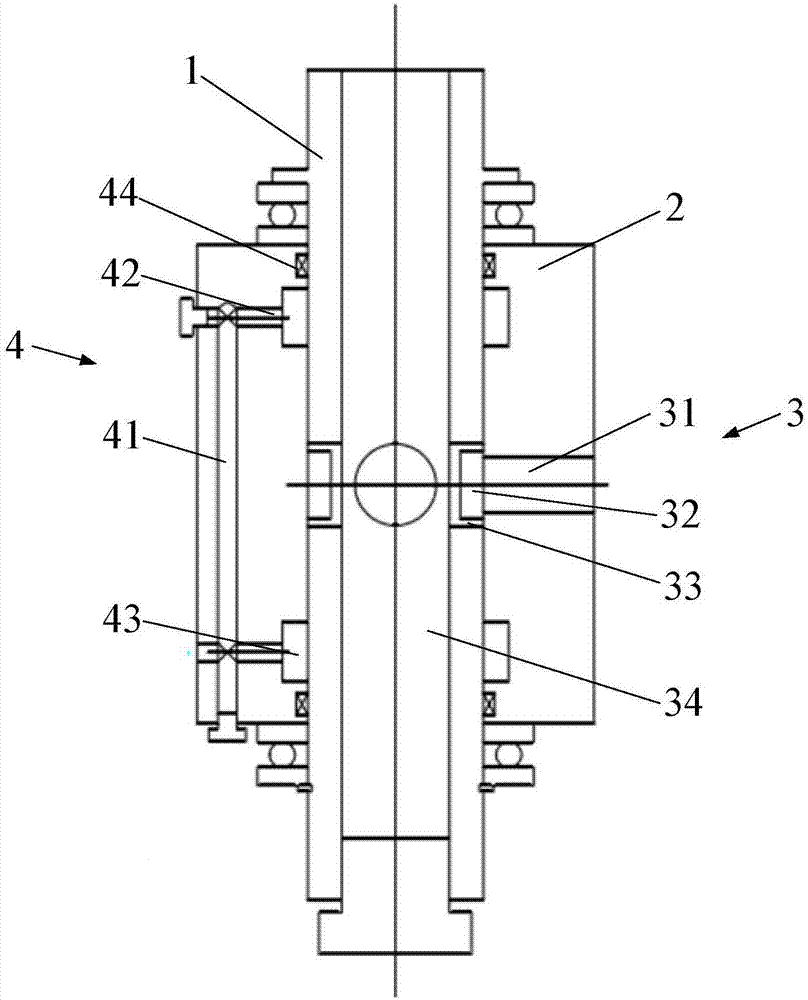
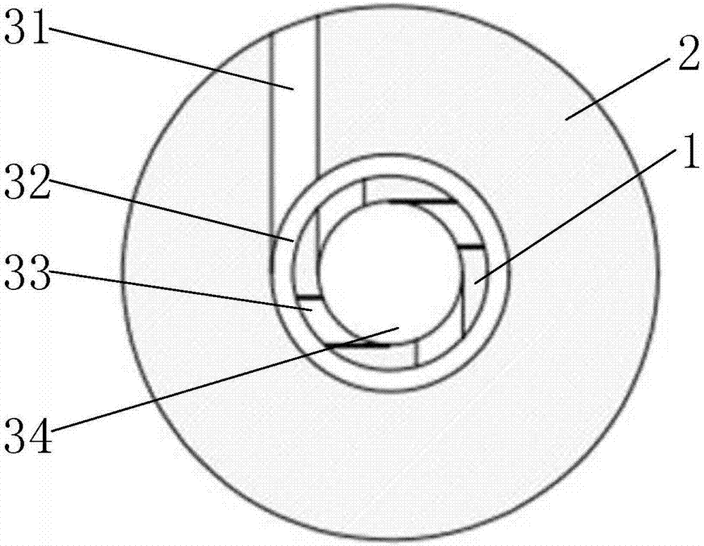
[0027] Such as figure 1 and figure 2 As shown, the rotary joint used to convey the two-phase flow containing solid abrasives in this embodiment includes an inner shaft 1, an outer casing 2 and a feeding assembly 3, the outer casing 2 is sleeved on the inner shaft 1, and the inner shaft 1 and the outer casing 2 Relatively rotatable, the delivery assembly 3 is installed on the inner shaft 1 and the outer jacket 2, and is used to deliver the high-pressure abrasive two-phase flow to the jet nozzle. In this embodiment, the casing 2 is provided with a high-pressure sealing assembly 4, which is used to deliver high-pressure fluid to the gap between the inner shaft 1 and the casing 2. The injection pressure of the high-pressure fluid is greater than the delivery press...


PUM


Abstract

The invention provides a rotating connector used for conveying a two-phase flow containing solid abrasives. The rotating connector used for conveying the two-phase flow containing the solid abrasives comprises an inner shaft, an outer sleeve arranged on the inner shaft in a sleeving manner, and a material conveying assembly arranged on the inner shaft and the outer sleeve in a penetrating manner; the outer sleeve is provided with a high pressure sealing assembly used for conveying high pressure fluid to a gap between the inner shaft and the outer sleeve; and the injecting pressure of the high pressure fluid is larger than the conveying pressure of the two-phase flow of the high pressure abrasives. The rotating connector used for conveying the two-phase flow containing the solid abrasives is especially used for the work condition of the two-phase flow containing abrasive particles, and has the beneficial effects that abrasion is small and flowing stability is good.

Description

technical field [0001] The invention relates to the field of rotary joints, in particular to a rotary joint for transporting two-phase flow containing solid abrasives. Background technique [0002] In actual work, the transportation of abrasive water jets is usually carried out by mixing solid abrasives with gaseous or liquid transportation media into a uniform solid-gas or solid-liquid two-phase flow, and applying a certain pressure. In abrasive water jet technology, the ability to crush, cut and abrade can be greatly improved by adding abrasives to water. Among them, the abrasive is added into the high-pressure water and mixed uniformly to form a high-pressure abrasive two-phase flow, and then sprayed from the nozzle is a pre-mixed abrasive water jet, and the pre-mixed abrasive water jet delivers a solid-liquid two-phase flow to the nozzle. ; The form of high-pressure water sprayed from the water nozzle and then added to the abrasive is a post-mixed abrasive water jet, an...

Claims


Application Information

Patent Timeline
Patent Type & Authority Applications(China)
IPC IPC(8): B24C5/00
CPCB24C5/00Y02P70/10
Inventor 刘飞香程永亮祝爽唐崇茂
Owner CHINA RAILWAY CONSTR HEAVY IND
Why Eureka
Try Eureka