Power system cooling structure

A cooling structure and power system technology, applied in the direction of power unit, electric power unit, transportation and packaging, etc., can solve the problems of reducing the cruising range and performance of the vehicle, high energy consumption, low efficiency, etc., and achieve optimized volume and cooling way, realize the effect of reducing weight and improving the cooling ability

Pending Publication Date: 2017-10-24
JIANGSU ENE CARBON ENERGY TECH CO LTD
View PDF0 Cites 2 Cited by
  • Summary
  • Abstract
  • Description
  • Claims
  • Application Information

AI Technical Summary

Problems solved by technology

The power system of the existing new energy pure electric vehicle is large in size, low in efficiency, and high in energy consumption.

Method used


Image

  • Power system cooling structure
  • Power system cooling structure

Examples


Embodiment Construction

[0014] In order to make the object, technical solution and beneficial technical effects of the present invention clearer, the present invention will be further described in detail below in conjunction with the accompanying drawings and specific embodiments. It should be understood that the specific implementations described in this specification are only for explaining the present invention, not for limiting the present invention.

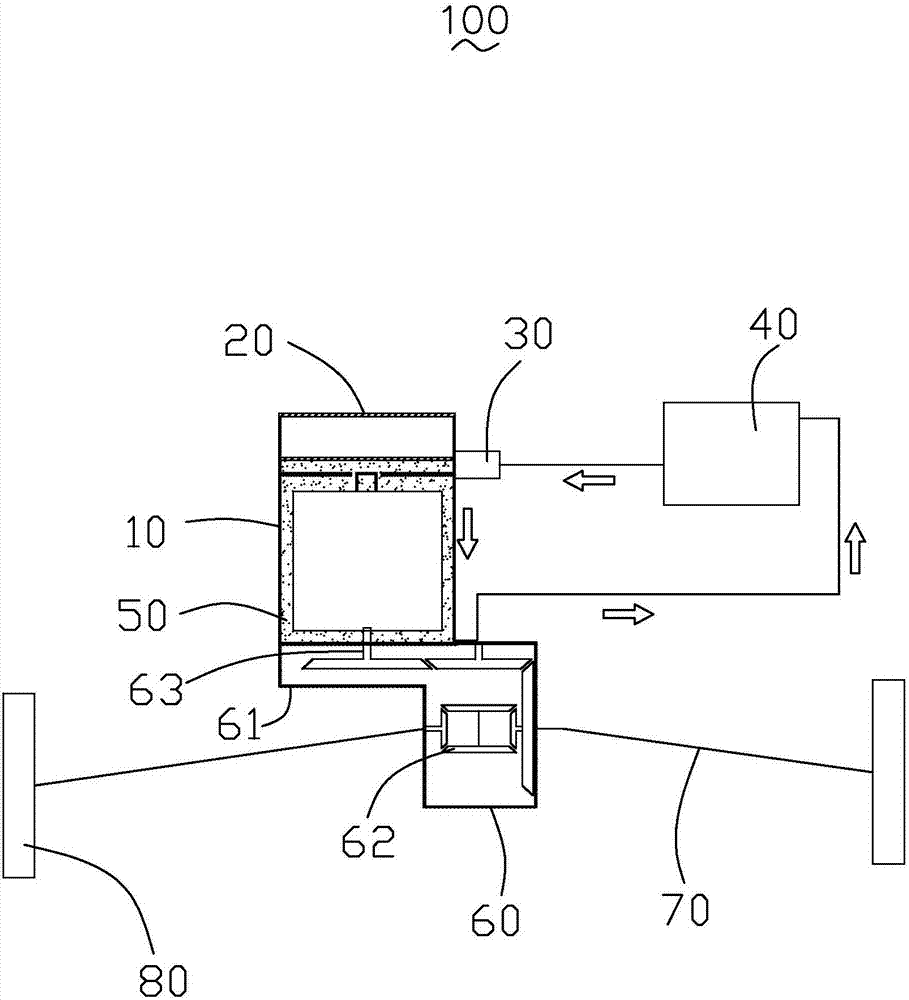
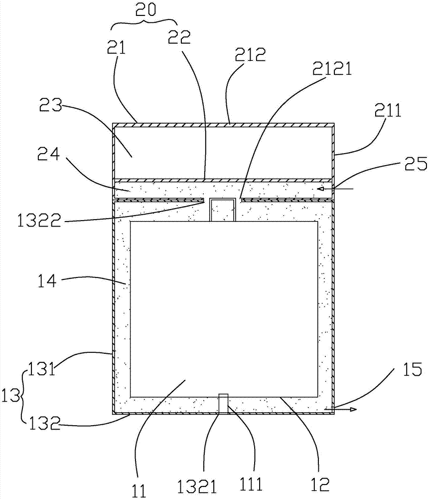
[0015] see figure 1 and figure 2 , the present invention provides a power system cooling structure 100 , including a drive motor 10 , a motor controller 20 , a pump 30 , a radiator 40 and a coolant 50 .

[0016] The drive motor 10 includes a stator and rotor 11, a motor inner shell 12 and a motor outer shell 13, the stator and rotor 11 are cylindrical and housed in the motor inner shell 12, and one end of the stator and rotor 11 is provided with an output shaft 111 , the output shaft 111 is connected to the speed reducer 60 . The reducer 60 inc...


PUM


Abstract

A cooling structure for a power system, including a drive motor, a motor controller, a pump, a radiator, and a coolant; the drive motor includes a motor inner shell and a motor shell, and the motor shell is sleeved outside the motor inner shell and forms a The first liquid cooling chamber for circulating the cooling liquid. The motor controller includes a motor controller housing and a partition accommodated in the motor controller housing; the partition divides the motor controller housing into a controller housing chamber and a second liquid cooling chamber, the The first liquid cooling chamber communicates with the second liquid cooling chamber. The cooling liquid flows from the pump into the second liquid cooling cavity of the motor controller, then flows into the first liquid cooling cavity of the driving motor, flows out to the radiator, and then flows back to the pump. The cooling structure of the power system provided by the present invention optimizes the volume and cooling mode of the power system, thereby realizing light weight of the system and improving the cooling capacity of the system.

Description

【Technical field】 [0001] The invention relates to the technical field of electric vehicles, in particular to a power system cooling structure. 【Background technique】 [0002] In recent years, electric vehicles have been popularized on a large scale. The power performance of electric vehicles is the most basic and important performance among various performances, which largely determines the transportation efficiency of electric vehicles. The existing new energy pure electric vehicle power system is large in size, low in efficiency, and high in energy consumption. The temperature rise of the system is large during summer operation, which greatly reduces the cruising range and performance of the vehicle. [0003] In view of this, it is necessary to provide a new power system cooling structure to overcome the above defects. 【Content of invention】 [0004] The purpose of the present invention is to provide a cooling structure for a power system, which optimizes the volume and...

Claims


Application Information

Patent Timeline
IPC IPC(8): B60K1/00
CPCB60K1/00B60K2001/006
Inventor 马晓辉钱龙孟江波
Owner JIANGSU ENE CARBON ENERGY TECH CO LTD
Why Eureka
Try Eureka