Crusher driven by linear motor
A linear motor and crusher technology, applied in the field of construction engineering, can solve the problems of low crushing efficiency, complicated equipment maintenance, and heavy equipment.
Inactive Publication Date: 2017-10-24
JINGMEN CHUANGJIA MACHINERY TECH CO LTD
View PDF4 Cites 4 Cited by
- Summary
- Abstract
- Description
- Claims
- Application Information
AI Technical Summary
Problems solved by technology
[0002] The concrete floor crushers currently used in the field of construction engineering are not only heavy equipment, but the crushing efficiency is not high, and the equipment maintenance is complicated.
Method used
View moreImage
Smart ImageViewing Examples

Examples
Embodiment Construction
[0009] Summary of the Invention The specific implementation of the lifting device has been described in detail and will not be repeated here. It should be explained that the crusher of the present invention is driven by a tubular linear motor. The working principle of this linear motor is a known technology and will not be repeated here. .
Login to View More PUM
 Abstract
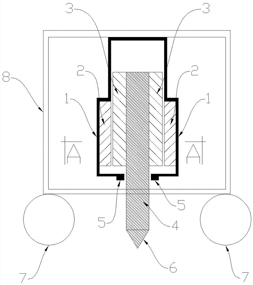
The invention provides a crusher driven by a linear motor. The crusher is mainly used for crushing concrete ground in the field of construction engineering, and is high in crushing efficiency and easy to maintain. The crusher mainly comprises a shell, a linear motor stator, a linear motor rotor, a center shaft, a bearing, a crushing head and a machine frame. According to the working principle, the linear motor rotor is connected with a forward power supply, and the linear motor rotor moves linearly and vertically upward along the linear motor stator and drives the central shaft and the crushing head to move linearly and vertically upward; when the linear motor rotor is connected with a reverse power supply, the linear motor rotor moves linearly and vertically downward along the linear motor stator and drives the central shaft and the crushing head to move linearly and vertically downward; the crushing head moves repeatedly to crush the concrete ground, and pushes the machine frame forward to crush the ground of the next place.
Description
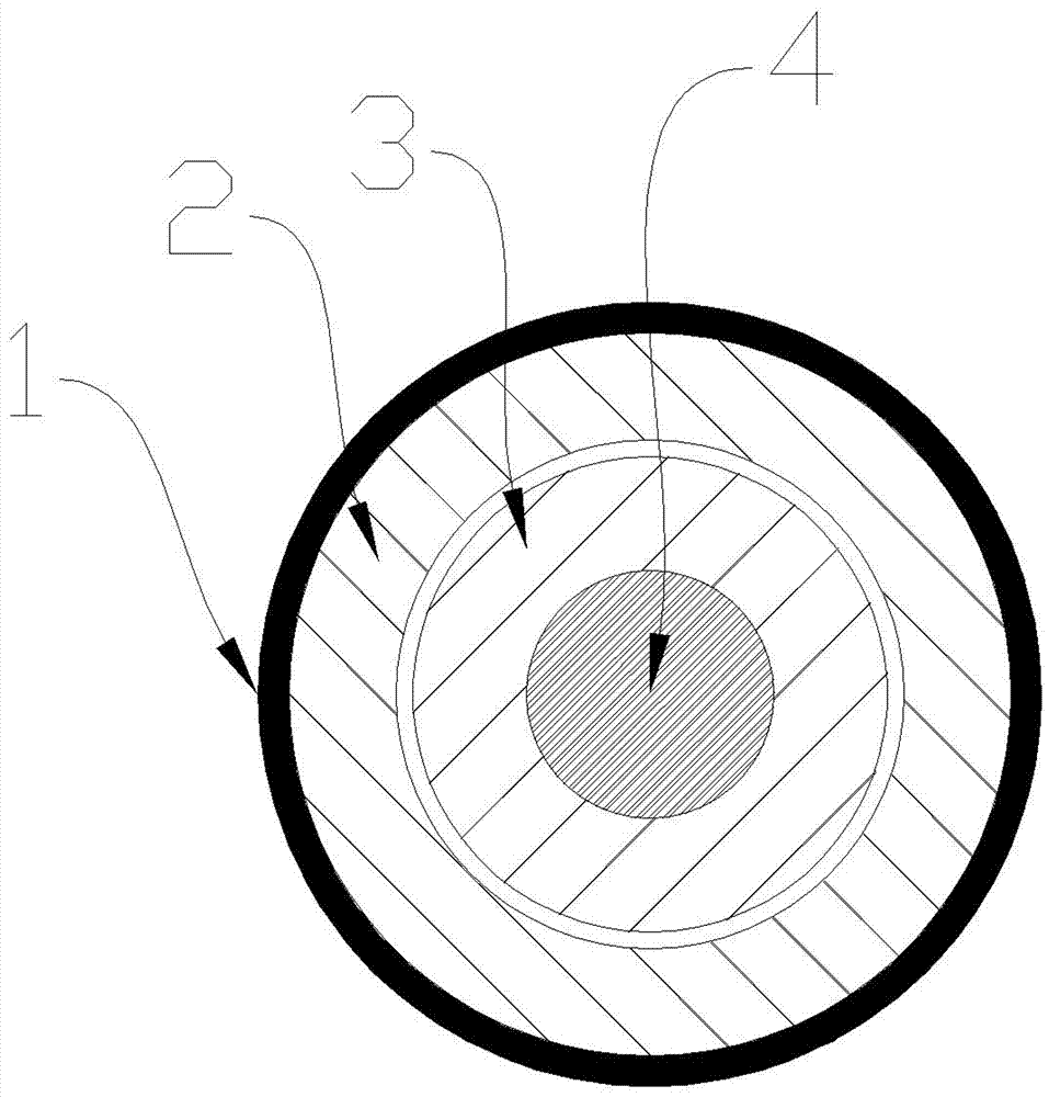
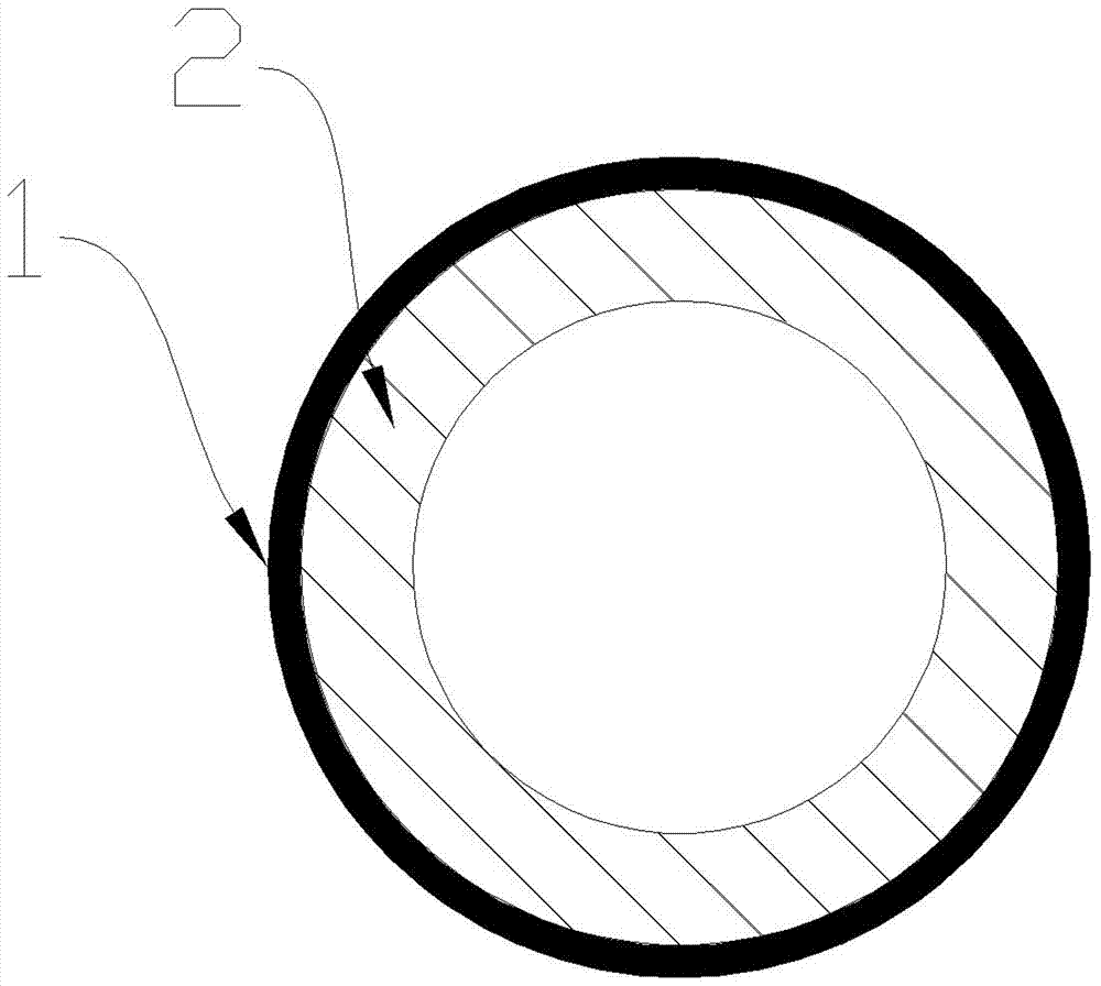
technical field [0001] The invention is mainly used for broken concrete ground in the field of construction engineering. Background technique [0002] The concrete floor crushers currently used in the field of construction engineering are not only heavy equipment, but also have low crushing efficiency and complicated equipment maintenance. Contents of the invention [0003] The present invention solves the above problems. It has high crushing efficiency and simple equipment maintenance; it mainly includes a casing (1), a linear motor stator (2), a linear motor mover (3), a central shaft (4), a bearing (5), The crushing head (6), the frame (8); the shell (1) is fixed to the frame (8), the frame (8) is fixed with wheels (7), the lower end of the shell (1) has a bearing (5), and the linear motor The stator (2) is fixed to the inner wall of the casing (1), the upper outer wall of the central shaft (4) is fixed to the inner wall of the linear motor mover (3), the lower part of...
Claims
Login to View More Application Information
Patent Timeline
 IPC IPC(8): E01C23/12
CPCE01C23/124
Inventor 彭宝安
Owner JINGMEN CHUANGJIA MACHINERY TECH CO LTD

PatSnap Eureka turns technology decisions into work you can execute. Powered by our Innovation Knowledge Graph, it runs expert workflows across engineering, life sciences, materials and intellectual property. Get your review-ready output in minutes.


