Pile measuring hole obstacle clearing device based on ultrasonic drill bit

A cleaning device, ultrasonic technology, applied in the direction of sheet pile wall, foundation structure engineering, construction, etc., to achieve the effect of strengthening hardness, good cleaning effect and reducing loss

Pending Publication Date: 2017-10-24
昂徕博智能科技(昆山)有限公司
View PDF7 Cites 4 Cited by
  • Summary
  • Abstract
  • Description
  • Claims
  • Application Information

AI Technical Summary

Problems solved by technology

[0004] The technical problem mainly solved by the present invention is: provide a kind of measuring pile hole obstacle cleaning device based on ultrasonic drill bit, can effectively dredge the blocked measurin

Method used


Image

  • Pile measuring hole obstacle clearing device based on ultrasonic drill bit

Examples


Embodiment

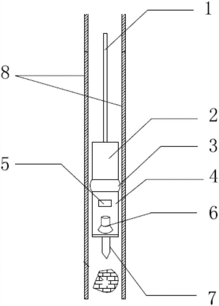
[0021] Embodiment: a kind of measuring pile hole obstacle cleaning device changer based on ultrasonic drill bit, such as figure 1 As shown, it includes a cable 1, a counterweight 2 and an ultrasonic drill 4. The front end of the ultrasonic drill 4 is provided with an ultrasonic drill 7, and the inside of the ultrasonic drill is provided with an ultrasonic generator 5 and a piezoelectric ceramic ultrasonic transducer. 6. The ultrasonic generator 5 is electrically connected to the cable 1, and the ultrasonic generator is electrically connected to the piezoelectric ceramic ultrasonic transducer 6 through a control circuit;

[0022] The cables, the counterweight and the ultrasonic drill are all located in the pile measuring hole 8 .

[0023] The piezoelectric ceramic ultrasonic transducer is arranged at the ultrasonic drill and is closely attached to the inner wall of the ultrasonic drill.

[0024] The counterweight 2 is connected to the ultrasonic drill 4 through a buffer device...


PUM


Abstract

The invention discloses a pile measuring hole obstacle clearing device based on an ultrasonic drill bit. The device comprises a cable, a counterweight block and an ultrasonic drilling machine; the ultrasonic drill bit is arranged at the front end of the ultrasonic drilling machine; an ultrasonic generator and a piezoelectric ceramic ultrasonic transducer are arranged in the ultrasonic drilling machine; the ultrasonic generator is electrically connected with the cable; the ultrasonic generator is electrically connected with the piezoelectric ceramic ultrasonic transducer through a control circuit; and the cable, the counterweight block and the ultrasonic drilling machine are all positioned in a pile measuring hole. The pile measuring hole obstacle clearing device based on the ultrasonic drill bit can effectively clear the blocked pile measuring hole, fills the blank on the clearing aspect of the pile measuring hole, solves the difficulty of incapability of measuring the pile measuring hole due to blockage, and is convenient in use, safe and efficient.

Description

technical field [0001] The invention belongs to the technical field of pile hole cleaning tools, in particular to a pile hole obstacle cleaning device based on an ultrasonic drill bit. Background technique [0002] Due to the advantages of no vibration, no soil extrusion, low noise, and suitable for use in densely built urban areas during construction, cast-in-place piles are widely used in construction. According to different hole-forming techniques, cast-in-situ piles can be divided into cast-in-place piles with dry operation, cast-in-place piles with mud retaining walls, and cast-in-place piles with manual digging. There is a small-diameter metal pipe inside the cast-in-place pile to measure whether there is a quality problem when the cast-in-situ pile is poured. [0003] However, due to natural and human factors, the pile holes of cast-in-situ piles are often blocked. The piles are several meters to tens of meters long, and the length of the pile holes is close to that ...

Claims


Application Information

Patent Timeline
IPC IPC(8): E02D13/08
CPCE02D13/08
Inventor 张威宋钢兵
Owner 昂徕博智能科技(昆山)有限公司
Why Eureka
Try Eureka