
Sealing structure and sliding oil sealing structure of bearing base of gas turbine engine

A technology of sealing structure and sealing gasket, which is applied in the direction of engine sealing, gas turbine device, engine lubrication, etc. It can solve the problems of small end face sealing area, poor sealing effect, and affecting sealing effect, so as to avoid leakage and improve the end face sealing area. Large, good sealing effect

Active Publication Date: 2017-10-24
AECC HUNAN AVIATION POWERPLANT RES INST
View PDF6 Cites 2 Cited by
  • Summary
  • Abstract
  • Description
  • Claims
  • Application Information

AI Technical Summary

Problems solved by technology

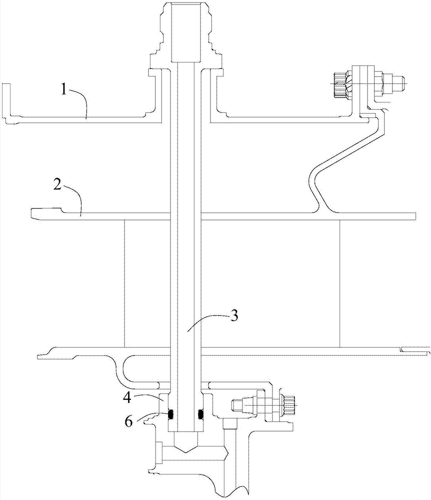
[0004] 1. Reference figure 1 As shown, a rubber ring 6 sealing structure is designed between the outer wall of the oil delivery pipe 3 and the bearing seat 4, and the deformation ability of the rubber ring 6 is used to seal; Low, generally can not exceed 400 degrees Celsius, the temperature in the turbine section of the engine is relatively high, the temperature at the junction of the oil pipe 3 and the bearing housing 4 can often reach above 500 degrees Celsius, at such a high temperature level, the apron 6 will carbonize and fail
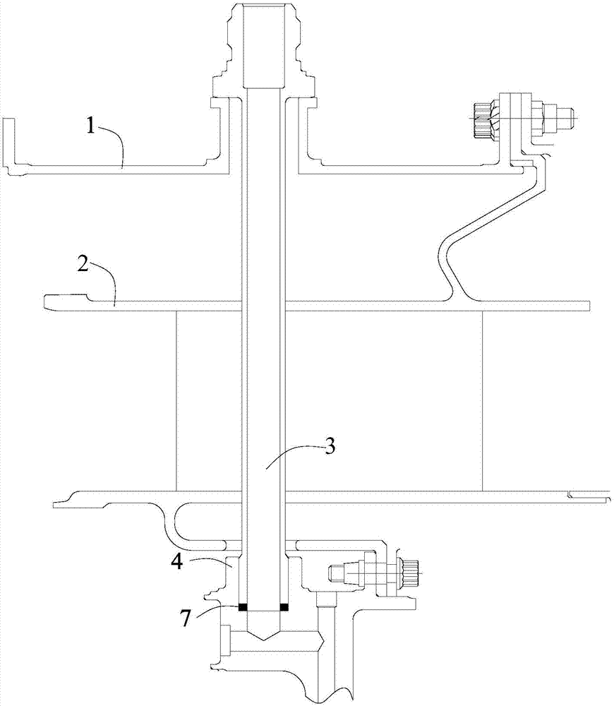
[0005] Two, reference figure 2 As shown, a gasket 7 is designed between the mating end faces of the oil delivery pipe 3 and the bearing seat 4, and the gasket 7 is slightly deformed by the pressing force between the oil delivery pipe 3 and the bearing seat 4, thereby achieving a sealing effect; but the sealing structure of the end face gasket 7 : During use, the gasket 7 is often deformed and damaged, which affects the sealing effect. In addition, because the thickness of the engine support plate is limited, the sealing area of ​​the end face is small and the sealing effect is poor.
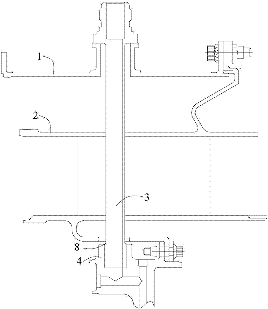
[0006] 3. Reference image 3 As shown, the oil delivery pipe 3 and the bearing seat 4 are welded into one, and the gap between the two is blocked by solder to form a weld 8, so as to achieve the sealing effect; but after the oil delivery pipe 3 and the bearing seat 4 are welded into one, the oil delivery pipe 3 and the Bearing seat 4 is integrated and cannot be disassembled, which is not conducive to later maintenance and repair

Method used


Image

  • Sealing structure and sliding oil sealing structure of bearing base of gas turbine engine
  • Sealing structure and sliding oil sealing structure of bearing base of gas turbine engine
  • Sealing structure and sliding oil sealing structure of bearing base of gas turbine engine

Examples


Embodiment Construction

[0033] Example embodiments will now be described more fully with reference to the accompanying drawings. Example embodiments may, however, be embodied in many forms and should not be construed as limited to the embodiments set forth herein; rather, these embodiments are provided so that this disclosure will be thorough and complete, and will fully convey the concept of example embodiments to those skilled in the art. The same reference numerals in the drawings denote the same or similar structures, and thus their detailed descriptions will be omitted.

[0034] An embodiment of the present invention provides a sealing structure for sealing a joint between a first component and a second component, the first component is formed with a first abutting surface, and the second component is formed with a second abutting surface , the first butt joint surface and the second butt joint surface are respectively an inner conical surface or an outer conical surface capable of mating and b...


PUM


Abstract

The invention discloses a sealing structure of a sliding oil sealing structure of a bearing base of a gas turbine engine. The sealing structure is used for sealing a joint of a first part and a second part; the first butt-joint surface is formed on the first part; a second butt-joint surface is formed on the second part; the first butt-joint surface and the second butt-joint surface are separately inner conical surfaces or outer conical surfaces which can be matched and in butt joint; and a sealing gasket is tiled between the first butt-joint surface and the second butt-joint surface. The sealing structure can be used to achieve the relatively good sealing effect.

Description

technical field [0001] The invention relates to the technical field of sealing, in particular to a sealing structure and a lubricating oil sealing structure of a gas turbine engine bearing seat. Background technique [0002] In existing gas turbine engines and various gas turbines, due to the high speed of the rotor, the bearings installed on the rotor will heat up seriously, and the heat will affect the life of the bearings. In order to lubricate and cool the bearings, it is necessary to provide enough lubricating oil for the bearings to lubricate cool down. This will rely on the oil pipe to introduce the lubricating oil from the outside into the bearing seat, and the sealing design needs to be considered at the junction to prevent the lubricating oil from leaking from the junction. [0003] At present, the following methods are usually used to realize the sealing between the oil delivery pipe and the bearing seat: [0004] 1. Reference figure 1 As shown, a rubber ring 6...

Claims


Application Information

Patent Timeline
Patent Type & Authority Applications(China)
IPC IPC(8): F02C7/28F02C7/06F16J15/08
CPCF02C7/06F02C7/28F16J15/0818F16J15/0881
Inventor 叶炜付晟白忠恺蔡斌陈润拓蔡琴
Owner AECC HUNAN AVIATION POWERPLANT RES INST
Learn More