Three-direction rigidity-adjustable vibration isolator

A vibration isolator and stiffness technology, applied in the field of vibration isolation and buffer devices of electromechanical equipment, can solve the problems of unsuitable vibration isolators, poor low-frequency vibration isolation effect, small static bearing capacity of vibration isolators, etc., and achieve stable material performance and Reliable, easy to achieve, wide range of effects

Active Publication Date: 2017-10-24
CHINA ELECTRONIC TECH GRP CORP NO 38 RES INST
View PDF5 Cites 17 Cited by
  • Summary
  • Abstract
  • Description
  • Claims
  • Application Information

AI Technical Summary

Problems solved by technology

However, the parameters of traditional vibration isolators are relatively fixed, which will bring three problems: 1. When the external loading platform or platform parameters change, the original vibration isolator will no longer Applicable, or even aggravate vibration; Second, in the design of electronic products, before the product weight, stiffness and other parameters are determined, it is impossible to correctly select the appropriate vibration damping device; Third, when designing vibration isolators, for the same type In order to meet the loading requirements of different platforms, it is necessary to develop a serialized vibration isolator sequence before it can be put into use
The higher the stiffness of the vibration isolator, the higher the initial frequency of vibration reduction of the vibration isolator, so the effect of low-frequency vibration isolation is relatively poor; Larger, the applicable range of load is smaller

Method used


Image

  • Three-direction rigidity-adjustable vibration isolator
  • Three-direction rigidity-adjustable vibration isolator
  • Three-direction rigidity-adjustable vibration isolator

Examples


Embodiment

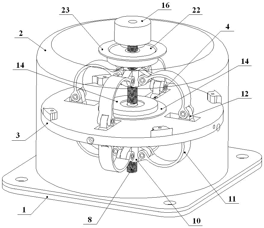
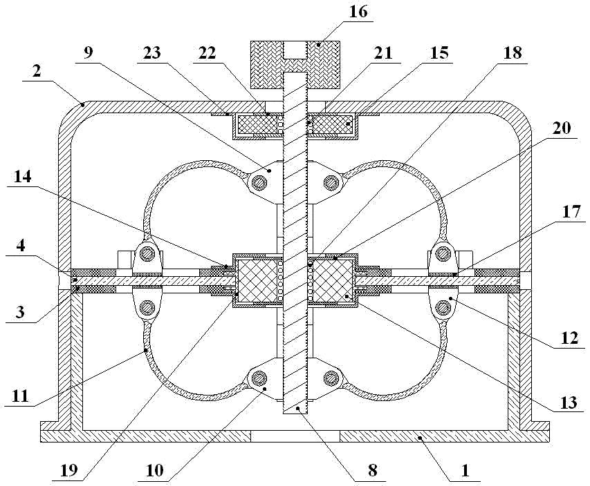
[0036] see figure 1 , a three-way stiffness adjustable vibration isolator includes a base 1, a shell 2, a functional platform 3, four rod-shaped horizontal sliding guide rails 4 and a vertical stiffness adjustment mechanism.

[0037] The base 1, the shell 2 and the functional platform 3 constitute the main structure; the shell 2 is a cover with an open bottom, and a mounting hole 5 is opened on the top, see image 3 ; The shell 2 is set on the base 1 to form the body, and the functional platform 3 is horizontally set in the middle of the body.

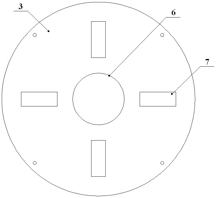
[0038] see Figure 4 , the central part of the functional platform 3 is provided with a central through hole 6 through the axial direction, and the functional platform 3 on the periphery of the central through hole 6 is evenly equipped with four rectangular holes 7, and the radial direction of the functional platform 3 corresponding to the four rectangular holes 7 Four guide rail threaded holes that pass through the central through h...


PUM


Abstract

The invention relates to a three-direction rigidity-adjustable vibration isolator. The vibration isolator comprises vertical rigidity-adjustable parts and transverse rigidity-adjustable parts, and specifically comprises an outer shell, a functional platform, a central screw, an upper central support, a lower central support, eight arched spring pieces, a central metal rubber net and four horizontal guide rails, wherein the eight arched spring pieces, the central screw, the upper central support and the lower central support form a vertical rigidity adjusting mechanism of the vibration isolator; and the central metal rubber net, the functional platform and the four horizontal guide rails form a transverse rigidity adjusting mechanism of the vibration isolator. According to the three-direction rigidity-adjustable vibration isolator, the interval between the upper central support and the lower central support is adjusted through rotating the central screw, the span among the four pairs of spring pieces is changed, and vertical rigidity is adjusted; the four sliding guide rails are rotated, acting force is applied to the central metal rubber net, friction between internal clearances of the central metal rubber net and a metal winding wire is changed, and transverse rigidity is adjusted; and the three-direction rigidity-adjustable vibration isolator is high in mounting adaptability and performance stability.

Description

technical field [0001] The invention belongs to the technical field of vibration isolation protection for vehicle-mounted, aircraft-mounted and ship-borne electronic equipment, and in particular relates to a vibration isolation buffer device for electromechanical equipment. technical background [0002] With the development of military science and technology, on the one hand, electronic equipment continues to develop towards integration, modularization and integration, and its requirements for vibration environments are becoming more and more stringent; on the other hand, due to the diversification and functionalization of loading platforms , and its vibration excitation to electronic equipment is becoming more and more complex. For example, various airborne electronic equipment will be subjected to vibration and shock transmitted from the aircraft platform during take-off, landing and flight. Excessive vibration or shock will directly affect the performance of electronic eq...

Claims


Application Information

Patent Timeline
IPC IPC(8): F16F7/00F16F7/104
CPCF16F7/00F16F7/104F16F2228/066
Inventor 彭超杨双根杨静胡劲松程林王晓红
Owner CHINA ELECTRONIC TECH GRP CORP NO 38 RES INST
Why Eureka
Try Eureka