
Test device for water flowing on pavement under action of tires

A test device, water flow technology, applied in the direction of measurement device, permeability/surface area analysis, suspension and porous material analysis, etc., can solve problems such as installation errors, troublesome installation and disassembly, and experimental failure, and achieve the effect of reducing measurement errors

Inactive Publication Date: 2017-10-24
SOUTHEAST UNIV
View PDF6 Cites 6 Cited by
  • Summary
  • Abstract
  • Description
  • Claims
  • Application Information

AI Technical Summary

Problems solved by technology

[0003] 1. The existing water seepage meter can only measure the water seepage coefficient of the road surface under hydrostatic pressure, but on the real road, the vehicle load travels on the road surface, the road surface water moves under the action of the vehicle load and generates dynamic water pressure on the road surface, the existing water seepage meter cannot be very Good simulation of the real road conditions;
[0004] 2. The existing water seepage meter can only measure the seepage coefficient under one state, that is, the pavement seepage coefficient under hydrostatic pressure, but cannot measure and compare the pavement seepage coefficients under various states;
[0005] 3. The existing water seepage meter will be in a tilted state on the road surface when there is a certain slope on the road surface, resulting in measurement errors;
[0006] 4. The existing water seepage meter does not adopt an integrated design, the installation and disassembly are very troublesome, and it is easy to fail the experiment due to installation errors

Method used


Image

  • Test device for water flowing on pavement under action of tires
  • Test device for water flowing on pavement under action of tires

Examples


Embodiment Construction

[0022] The present invention will be further described in detail below through the specific examples, the following examples are only descriptive, not restrictive, and cannot limit the protection scope of the present invention with this.

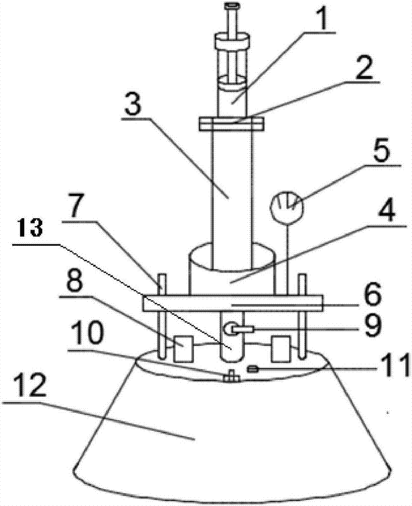
[0023] like figure 1 As shown, a tire-pavement connected water flow test device includes a pressurized air pump 1 , a water seepage meter and a water-vibrating motor 4 . The water seepage instrument comprises a pressurized measuring cylinder 3, a water seepage pipe 13, and a cavity base 12, and the cavity base 12 of the present invention is a circular truncated shape. An adjustment knob 10 for adjusting the horizontal inclination is installed on the cavity base 12 to adapt to road conditions with different slopes, and a horizontal bubble meter 11 is installed on the upper end of the cavity base 12 . The bottom of the cavity base 12 is provided with a bottom sealing ring 14 . The cavity base 12 is provided with a water seepage cavity 15, an...


PUM


Abstract

The invention discloses a test device for water flowing on pavement under action of tires. The test device comprises a pressurization suction pump (1), a seepage meter and a water vibration motor (4), wherein the seepage meter comprises a pressurization measuring cylinder (3), a seepage pipe (13) and a cavity base (12), a seepage cavity (15) is formed in the cavity base, one end of the seepage pipe is communicated with the seepage cavity, the other end of the seepage cavity is communicated with the pressure measuring cylinder, and a valve (9) is arranged on the seepage pipe; a port, away from the seepage pipe, of the pressurization measuring cylinder is communicated with the pressurization suction pump (1) through a connecting groove (2), the water vibration motor is mounted on the pressurization measuring cylinder, and an electronic water meter (5) is mounted in a port, communicated with the seepage pipe, of the pressurization measuring cylinder. The test device of the communicated water flow of pavement under tires can simulate the seepage situation of the asphalt pavement after dynamic water pressure is generated under the load action of the tires, and water seepage coefficients of the asphalt pavement are measured under the condition, so that test accuracy can be improved, actual measurement requirements are met, and broad application prospect is realized.

Description

technical field [0001] The invention belongs to the technical field of road engineering, and relates to a device for simulating water seepage of an asphalt pavement after hydrodynamic pressure is generated under the action of a tire load and measuring the water seepage coefficient of the asphalt pavement under this condition, in particular to a tire pavement connected water flow test device. Background technique [0002] Pavement water seepage coefficient is one of the key technical indicators to measure pavement drainage performance. The accuracy of pavement water seepage coefficient measurement is related to the safety of traffic in rainy days and the degree of road water damage. But there are following deficiencies in existing water seepage meter at present: [0003] 1. The existing water seepage meter can only measure the water seepage coefficient of the road surface under hydrostatic pressure, but on the real road, the vehicle load travels on the road surface, the road ...

Claims


Application Information

Patent Timeline
IPC IPC(8): G01N15/08
CPCG01N15/0806G01N15/0826
Inventor 黄晓明马静雯黄若昀朱晟泽朱宇昊殷大泉
Owner SOUTHEAST UNIV
Learn More