A method for parameter setting and synchronous display of a rail flaw detection gate

A technology of synchronous display and gate, applied in measurement devices, transportation and packaging, railway auxiliary equipment, etc., can solve the problems of unintuitive parameter setting, operator dependence, unfavorable damage, etc., to improve the efficiency of rail flaw detection and parameter setting. Intuitive, display intuitive effects

Active Publication Date: 2020-08-18
ZHUZHOU TIMES ELECTRONICS TECH CO LTD
View PDF5 Cites 0 Cited by
  • Summary
  • Abstract
  • Description
  • Claims
  • Application Information

AI Technical Summary

Problems solved by technology

[0009] In view of this, the purpose of the present invention is to provide a method for parameter setting and synchronous display of rail flaw detection gates, so as to solve the problem that the existing parameter setting method is too dependent on the experience of the operator, and the parameter setting is not intuitive (even unreasonable), which is not conducive to flaw detection. Systematic detection of specific damage on specific parts of rails

Method used


Image

  • A method for parameter setting and synchronous display of a rail flaw detection gate
  • A method for parameter setting and synchronous display of a rail flaw detection gate
  • A method for parameter setting and synchronous display of a rail flaw detection gate

Examples


Embodiment Construction

[0039] For the sake of reference and clarity, the technical terms, abbreviations or abbreviations used below are recorded as follows:

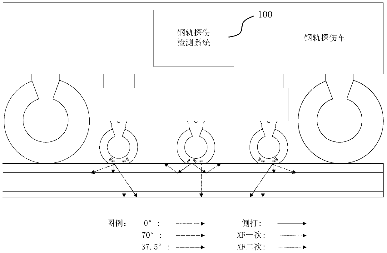
[0040] Probing wheel: a wheel structure, the shaft center frame is equipped with several ultrasonic chips with different detection angles, and the outer film of the tire is filled with coupling fluid. When the locomotive is running, the probing wheel rolls along the rail, and the moving direction of the detection chip is parallel to the rail ;

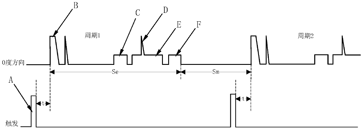
[0041] A-type display: It is a display method for displaying analog ultrasonic signals through an oscilloscope;

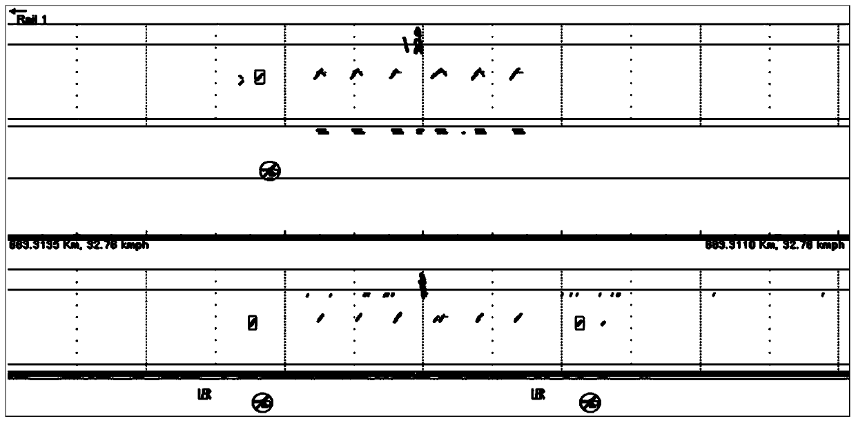
[0042] B-type display: It is a display method that visually displays the information of ultrasonic reflection points inside the rail through images.

[0043] In order to make the purpose, technical solutions and advantages of the embodiments of the present invention more clear, the technical solutions in the embodiments of the present invention will be clearly and completely described below ...


PUM


Abstract

The invention discloses a steel rail flaw detection gate parameter setting and synchronous display method. The method comprises the following steps: adjusting a detectable region in a corresponding steel rail by adjusting gate delay and a width parameter value of an ultrasonic echo signal by virtue of a gate parameter setting module of an upper computer; downloading the gate delay and the width parameter value to a real-time control unit, converting the ultrasonic echo signal into an echo digital signal through analog-to-digital conversion, and then inputting into a digital signal processing unit; and controlling the digital signal processing unit to adjust gate delay and width of the echo digital signal by the real-time control unit, converting the echo digital signal subjected to gate delay and width adjustment treatment into an analog A display signal through digital-to-analog conversion, and carrying out synchronous waveform display by virtue of an A display unit. The method disclosed by the invention can be used for solving the technical problems that ultrasonic parameter setting of an existing steel rail flaw detection system relies on experience of an operator excessively, parameter setting is not visual and a flaw of a specific part of a steel rail cannot be conveniently detected by the flaw detection system.

Description

technical field [0001] The invention relates to the technical field of rail engineering machinery, in particular to a rail flaw detection gate parameter setting and synchronous display method applied to a rail flaw detection vehicle. Background technique [0002] Large-scale ultrasonic rail flaw detection vehicle is a common detection tool for detecting internal damage of rails. Based on the principle of ultrasonic reflection, the large-scale wheeled rail flaw detection vehicle uses high-voltage excitation pulses to excite ultrasonic probe chips, and the ultrasonic signals generated pass through the detection wheel fluid and wheel film. , The coupled liquid layer is incident on the rail, and the ultrasonic chip at different angles can detect different rail areas. figure 1 shown. The ultrasonic signal propagates in the rail, and returns when it encounters damage or rail bottom, and the returned ultrasonic echo signal is processed by digital signal to form damage graphic info...

Claims


Application Information

Patent Timeline
Patent Type & Authority Patents(China)
IPC IPC(8): G01N29/38G01N29/06B61K9/10
CPCB61K9/10G01N29/069G01N29/38G01N2291/0289G01N2291/044G01N2291/2623
Inventor 李红梁罗江平王文星夏浪曹经纬邓亦农朱红飞魏芳坤谭群林谭勇罗文胜
Owner ZHUZHOU TIMES ELECTRONICS TECH CO LTD
Why Eureka
Try Eureka