Method for location of following target and following device
What is AI technical title?
AI technical title is built by PatSnap AI team. It summarizes the technical point description of the patent document.
A target and equipment technology, applied in the field of robotics, can solve the problems of poor relative position information accuracy, long time consumption, increased risk of luggage loss, etc.
Active Publication Date: 2017-10-24
LINGDONG TECH BEIJING CO LTD
View PDF6 Cites 14 Cited by
Summary
Abstract
Description
Claims
Application Information
AI Technical Summary
This helps you quickly interpret patents by identifying the three key elements:
Problems solved by technology
Method used
Benefits of technology
Problems solved by technology
[0004] The inventor of the present application found in research that the suitcase in the related art has at least the following problems: the radio frequency positioning module used for positioning is easily interfered by the surrounding environment of the suitcase, resulting in the obtained relative position information with the user The accuracy is poor, which leads to the fact that the suitcase cannot accurately follow the user's walking, which requires the user to observe and maintain the suitcase in real time, which brings a series of problems to the user, such as cumbersome operation and long time-consuming, and increases the number of suitcases. risk of loss
Method used
Image
Click on the blue label to locate the original text in one second.
Reading with bidirectional positioning of images and text.
Examples
Embodiment approach 1
[0123] Embodiment 1: Convert the image to color spaces such as RGB (RGB color mode), HSV (Hue, Saturation, Value, color model), LAB (color model) and so on. Construct M regions in each color space, and each region corresponds to a range in the three-dimensional space. Corresponding to the M-dimensional feature vector F, F is initialized as a 0 vector.
[0124] Judge each pixel point p(x, y), where (x, y) is the coordinate of the pixel point p in the image. If the color value of the pixel p(x,y) belongs to the i-th region, then: F_i=F_i+Q(x,y). Among them, Q(x,y)∝N(W / 2,H / 2,σ_1 ^2,σ_2^2,ρ). Among them, F_i represents the i-th dimension in the vector F, N() is a two-dimensional Gaussian distribution, W and H are the width and height of the pedestrian image, σ_1^2, σ_2^2 are the variances of x and y, respectively, ρ is a constant. Finally, the feature vectors on all color spaces are concatenated as the identification feature vector on this bar.
Embodiment approach 2
[0126] Divide the image into several small blocks horizontally on the bar. All the pixels on each small block are projected onto the N-dimensional color namespace, and then the proportion distribution of the color namespace on the small block is calculated to obtain an N-dimensional vector.
[0127] On each small block, weight the N-dimensional vector obtained in the previous step, and the weight is: Q(x,y)∝N(W / 2,H / 2,σ_1^2,σ_2^2,ρ). Where (x, y) is the coordinate of the center of the small block on the image. N() is a two-dimensional Gaussian distribution, W and H are the width and height of pedestrian images, σ_1^2, σ_2^2 are the variances of x and y, respectively, and ρ is a normal constant. Finally, the weighted vectors of all small blocks are concatenated as the identification feature vector on this bar.
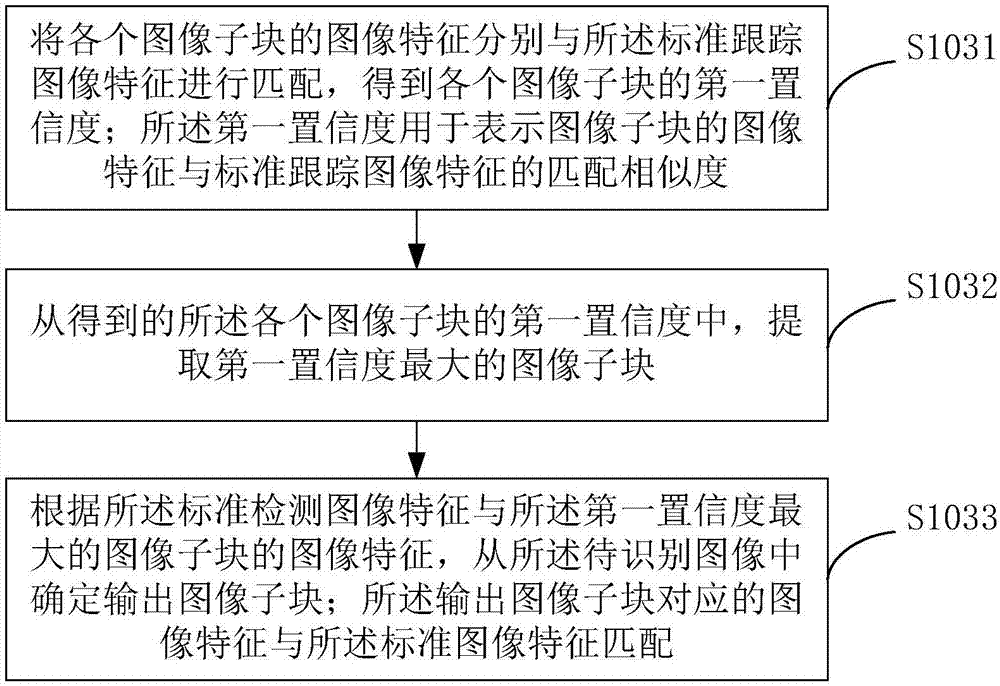
[0128] refer to Figure 4 , the above step 103, according to the standard image features of the following target and the detected image features of each image sub-blo...
PUM
Abstract
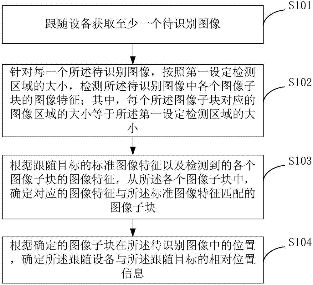
The present invention provides a method for location of following target and a following device. An image to be identified is obtained based on vision, image subblocks corresponding to image areas at each position in the image to be identified is subjected to image feature matching through standard image features, an image subblock having image features matching the standard image features is determined, and the relative position information of a following device and a following target is determined according to the position information of the image subblock in the image to be identified. A mode of the relative position information of the location following device of an image to be identified and the following target based on the vision is not easy to be interfered by a surrounding environment, the location precision is high, the following device is ensured to accurately track the following target, the following device does not need real-time observation and maintenance by users, and therefore the problems are avoided that user operation is complex, the time consumption is long and the like, the utilization efficiency of user tripping time is improved, and the risk of loss of a luggage box is greatly reduced.
Description
technical field [0001] The invention relates to the field of robots, in particular to a method for locating a following target and a following device. Background technique [0002] With the development of the economy, people's living standards are also constantly improving, and users' travel is becoming more and more common, such as business trips at work or travel in life, users usually have to carry suitcases when traveling, and travel suitcases The functional requirements are getting higher and higher. For example, for users who need to go out for a long time, they hope to free their hands and reduce the burden. [0003] Related technology CN201610329435.X provides a mobile robot (specifically, a suitcase) with the function of autonomously following and avoiding obstacles. The suitcase obtains the relative position information with the user through the radio frequency positioning module, and controls the change according to the obtained relative position information. Th...
Claims
Application Information
Patent Timeline
Application Date:The date an application was filed.
Publication Date:The date a patent or application was officially published.
First Publication Date:The earliest publication date of a patent with the same application number.
Issue Date:Publication date of the patent grant document.
PCT Entry Date:The Entry date of PCT National Phase.
Estimated Expiry Date:The statutory expiry date of a patent right according to the Patent Law, and it is the longest term of protection that the patent right can achieve without the termination of the patent right due to other reasons(Term extension factor has been taken into account ).
Invalid Date:Actual expiry date is based on effective date or publication date of legal transaction data of invalid patent.

