A continuous reactive power compensation circuit and control method

A compensation circuit and capacitor technology, applied in reactive power adjustment/elimination/compensation, reactive power compensation, circuit devices, etc., can solve the problem of inability to realize grid reactive power control, etc., to improve the effect of dynamic reactive power control, reactive power The effect of large compensation capacity and strong controllability

Active Publication Date: 2020-11-24
CHINA THREE GORGES UNIV
View PDF4 Cites 0 Cited by
  • Summary
  • Abstract
  • Description
  • Claims
  • Application Information

AI Technical Summary

Problems solved by technology

Combining the technical status of the current reactive power compensation equipment and the actual characteristics of the reactive power demand of the power grid, the existing technology cannot meet the needs of reactive power control of the power grid in different time dimensions

Method used


Image

  • A continuous reactive power compensation circuit and control method
  • A continuous reactive power compensation circuit and control method
  • A continuous reactive power compensation circuit and control method

Examples


Embodiment Construction

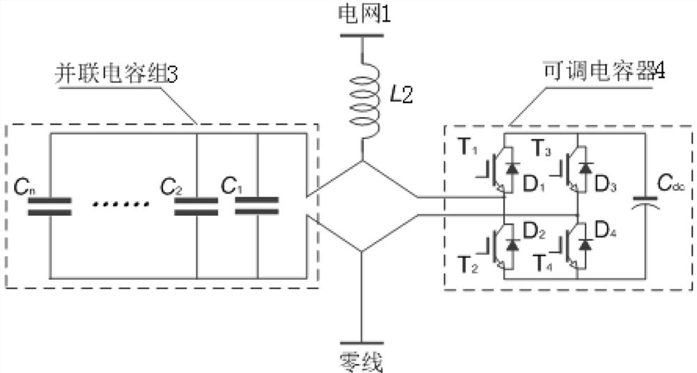
[0026] Such as figure 1 As shown, in the embodiment of the present invention: a continuous reactive power compensation circuit, including a grid 1, a reactor L2, a parallel capacitor bank 3 and an adjustable capacitor 4; one end of the reactor L2 is connected to the grid 1, and the other end is connected to the parallel capacitor Group 3 is connected to adjustable capacitor 4; parallel capacitor group 3 is composed of C 1 、C 2 …C n composed of AC capacitors, C 1 、C 2 …C n AC capacitors are connected in parallel with each other; the adjustable capacitor 4 consists of T 1 , T 2 , T 3 , T 4 , Diode D 1 、D 2 、D 3 、D 4 and a DC capacitor C dc Composition, T 1 , T 2 , T 3 , T 4 The collectors of the diodes D 1 、D 2 、D 3 、D 4 connected to the cathode, T 1 , T 2 , T 3 , T 4 The emitters are connected to the diode D 1 、D 2 、D 3 、D 4 connected to the anode of T 1 with D 1 , T 2 with D 2 , T 3 with D 3 , T 4 with D 4 Form four groups of switch modules...


PUM


Abstract

A continuous reactive power compensation circuit, comprising a power grid, a reactor L, a parallel capacitor bank and an adjustable capacitor; the reactor L One end is connected to the power grid, and the other end is connected to a parallel capacitor bank and an adjustable capacitor. The parallel capacitor bank contains n AC capacitors, and connected in parallel with each other, the adjustable capacitor consists of 4 IGBTs (T 1 -T 4 ), 4 diodes (D 1 -D 4 ) and 1 DC capacitor C dc composition; by monitoring and analyzing the reactive power of the power grid, the reactive power compensation amount in different periods is decomposed into two parts: constant amount and fluctuating amount. Compensation: It not only has the advantages of high control precision and fast response speed, but also can be easily expanded to increase the compensation capacity, thereby improving the comprehensive compensation capability of the device.

Description

technical field [0001] The invention relates to the technical field of electrical control, in particular to a continuous reactive power compensation circuit and a control method. Background technique [0002] Reactive power compensation is the main way to control the reactive power balance of the power grid. It is also the key equipment to ensure the safe, stable and reliable operation of the power grid. It mainly includes: static var compensator (SVC) and static var generator (STATCOM). At present, SVC is generally controlled by thyristors, including thyristor switched capacitors (TSC) and thyristor controlled reactors (TCR). However, the compensation accuracy is low, the response speed is slow, and the harmonic content is high; STATCOM is generally controlled by an insulated gate bipolar transistor (IGBT), which has a good compensation effect and low current harmonic content, but the compensation capacity is not high and the control is more complicated. In practice, the d...

Claims


Application Information

Patent Timeline
Patent Type & Authority Patents(China)
IPC IPC(8): H02J3/18
CPCH02J3/1842Y02E40/30
Inventor 魏业文曹斌刘国特王辉程江洲
Owner CHINA THREE GORGES UNIV
Why Eureka
Try Eureka