
Automatic chamfering device

A technology of chamfering and equipment, which is applied in the direction of metal processing equipment, grinding/polishing equipment, grinding feed movement, etc. It can solve problems such as unstable chamfering quality, large influence of manual chamfering, and uncompact equipment structure. Achieve the effects of wide application range, good chamfering quality and compact equipment

Pending Publication Date: 2017-10-27
京磁材料科技股份有限公司
View PDF8 Cites 12 Cited by
  • Summary
  • Abstract
  • Description
  • Claims
  • Application Information

AI Technical Summary

Problems solved by technology

[0002] At present, manual chamfering is mostly used for chamfering of square workpieces, the chamfering efficiency is low, and manual chamfering is greatly affected by human subjective factors, and the quality of chamfering is unstable
Although the existing chamfering equipment solves the problem of unstable chamfering quality, most of them chamfer the two long opposite sides of the workpiece step by step. The chamfering efficiency is still low, and the equipment structure is not compact and takes up a lot of space. Big

Method used


Image

  • Automatic chamfering device
  • Automatic chamfering device
  • Automatic chamfering device

Examples


Embodiment Construction

[0036] The present invention will be described in further detail below in conjunction with the embodiments and accompanying drawings, so that those skilled in the art can implement it with reference to the description.

[0037] It should be noted that the experimental methods described in the following embodiments, unless otherwise specified, are conventional methods, and the reagents and materials, if not otherwise specified, can be obtained from commercial sources; in the description of the present invention, The terms "landscape", "portrait", "top", "bottom", "front", "rear", "left", "right", "vertical", "horizontal", "top", "bottom", The orientation or positional relationship indicated by "inner", "outer", etc. is based on the orientation or positional relationship shown in the drawings, which is only for the convenience of describing the present invention and simplifying the description, and does not indicate or imply that the referred device or element must have Certain ...


PUM


Abstract

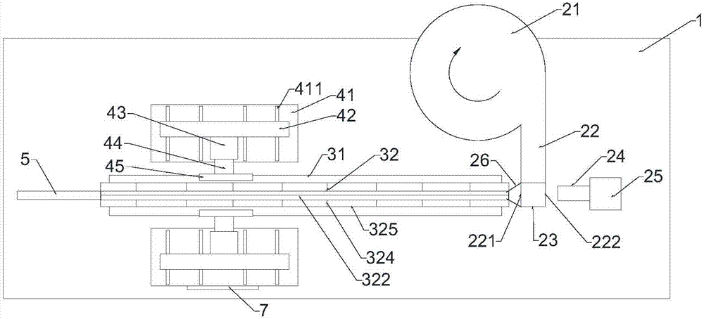
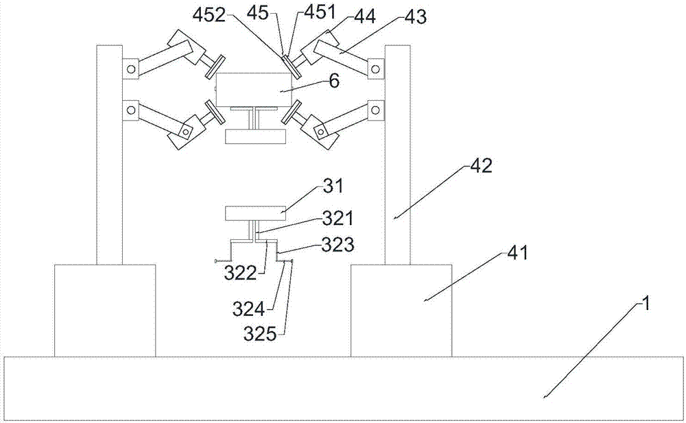
The invention discloses an automatic chamfering device, which comprises a machine base, a feeding mechanism, a conveying mechanism, two lead rails, multiple vertical rods, multiple first cross rods, second cross rods, and two chamfering mechanisms; the conveying mechanism comprises a belt conveyer; two lead rails are symmetrically arranged along the central line of a conveying belt of the belt type conveyer; any one lead rail comprises a vertical plate perpendicular to the conveying belt and a cross plate in parallel to the conveying belt, wherein the bottom part of the cross plate is fixedly connected with the upper part of the vertical plate; multiple vertical rods are perpendicular to the conveying belt, and the lower end of any one vertical rod is fixedly connected to one end of the cross plate closing to the edge of the conveying belt; multiple first cross rods are in parallel to the conveying belt, and corresponding to the vertical rods one by one; one end of any one first cross rod closing to the central line of the conveying belt is fixedly connected with the upper ends of the vertical rods; the second cross rods are hinged with the other ends of the first cross rods. The automatic chamfering device has the advantages of good chamfering quality, high efficiency, compact and small equipment, and others.

Description

technical field [0001] The invention relates to the field of mechanical equipment. More specifically, the present invention relates to an automatic chamfering device. Background technique [0002] At present, manual chamfering is mostly used for chamfering of square workpieces, the chamfering efficiency is low, and manual chamfering is greatly affected by human subjective factors, and the quality of chamfering is unstable. Although the existing chamfering equipment solves the problem of unstable chamfering quality, most of them chamfer the two long opposite sides of the workpiece step by step. The chamfering efficiency is still low, and the equipment structure is not compact and takes up a lot of space. Big. Contents of the invention [0003] It is an object of the present invention to solve at least the above-mentioned problems and to provide at least the advantages which will be described later. [0004] Another object of the present invention is to provide a chamferi...

Claims


Application Information

Patent Timeline
Patent Type & Authority Applications(China)
IPC IPC(8): B24B9/00B24B41/02B24B41/00B24B27/00B24B41/06
CPCB24B9/00B24B27/0076B24B41/005B24B41/02B24B41/06
Inventor 武亚凯
Owner 京磁材料科技股份有限公司
Learn More