Grinding device for hydroelectric power generation equipment

An equipment and water conservancy technology, which is applied in the field of grinding devices for water conservancy and power generation equipment, can solve the problems of poor control of strength, low grinding efficiency, time-consuming and labor-intensive, etc.

Active Publication Date: 2019-05-17
SOUTHERN POWER GRID PEAK LOAD & FREQUENCY REGULATION GENERATING CO LTD
View PDF7 Cites 0 Cited by
  • Summary
  • Abstract
  • Description
  • Claims
  • Application Information

AI Technical Summary

Problems solved by technology

[0005] In order to overcome the shortcomings of the current grinding equipment, such as low grinding efficiency, poor control of strength, and time-consuming and labor-intensive problems, the technical problem to be solved by the invention is to provide a kind of grinding equipment for hydroelectric power generation that has high grinding efficiency, effective control of strength, and saves time and effort. device

Method used


Image

  • Grinding device for hydroelectric power generation equipment
  • Grinding device for hydroelectric power generation equipment
  • Grinding device for hydroelectric power generation equipment

Examples


Embodiment 1

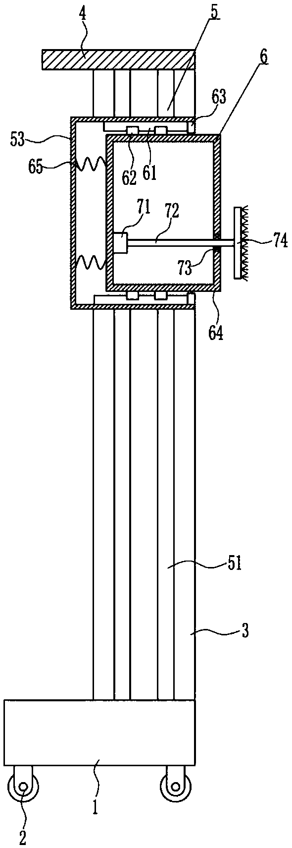
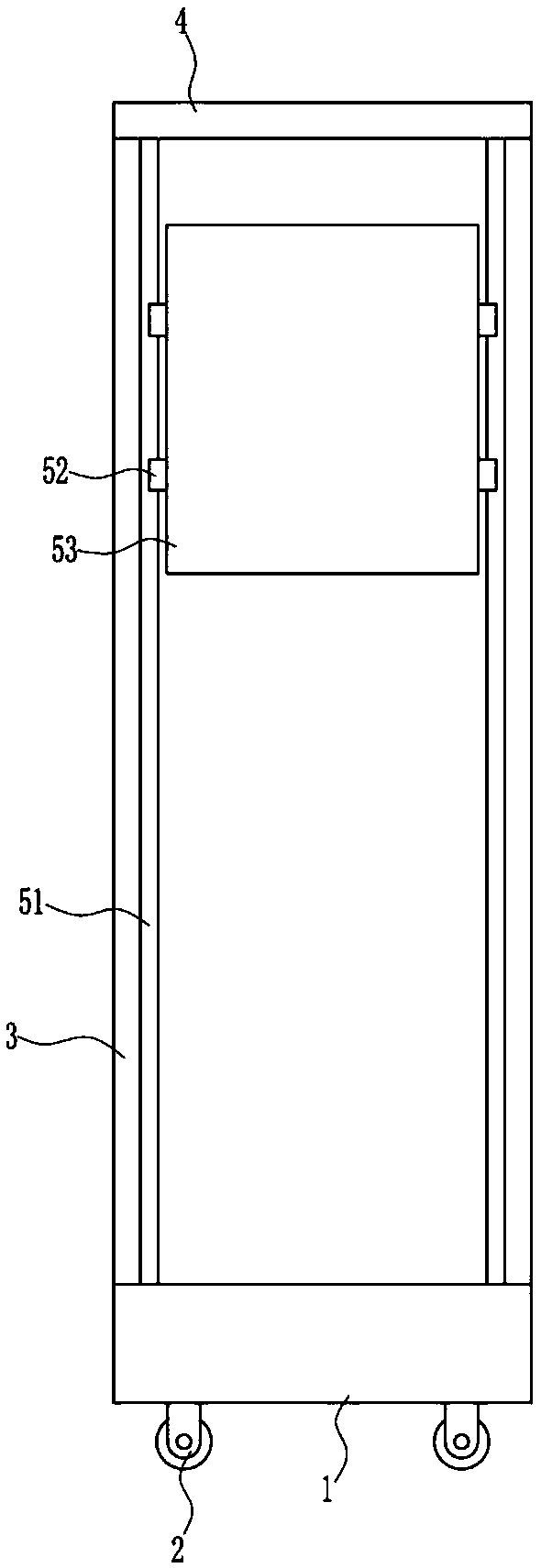
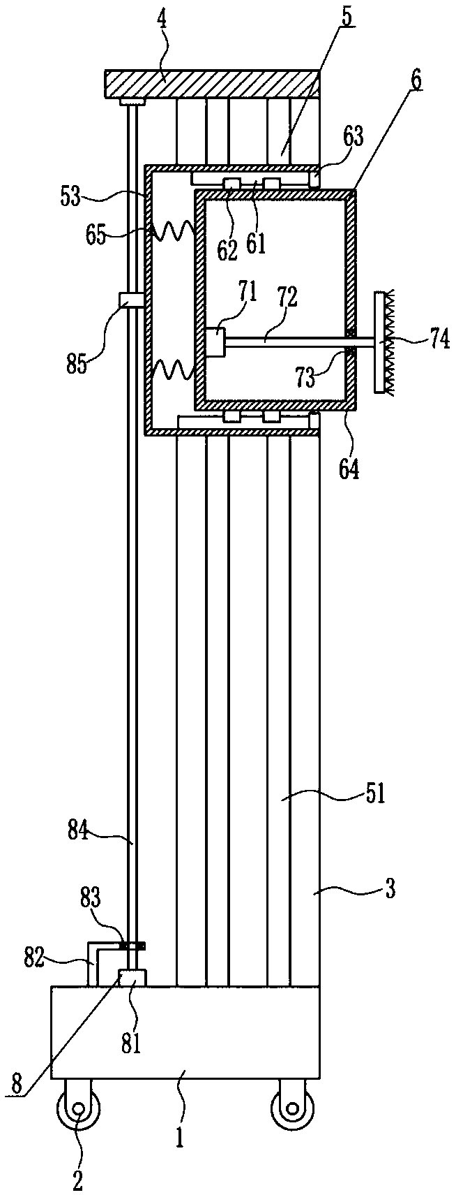
[0036] A kind of equipment grinding device for hydroelectric power generation, such as Figure 1-8 As shown, it includes a bottom plate 1, a wheel 2, a support plate 3, a top plate 4, a lifting device 5, a sliding device 6 and a first grinding device 7, and the four corners of the bottom of the bottom plate 1 are all equipped with wheels 2 by means of bolt connections, and the bottom plate 1 The front and rear ends on the right side of the top are connected with a support plate 3 by means of bolt connection, the top of the front and rear support plates 3 is connected with a top plate 4, and a lifting device 5 is provided between the front and rear support plates 3, and a sliding device 5 is provided in the lifting device 5. Device 6, the sliding device 6 is provided with a first grinding device 7.

Embodiment 2

[0038] A kind of equipment grinding device for hydroelectric power generation, such as Figure 1-8 As shown, it includes a bottom plate 1, a wheel 2, a support plate 3, a top plate 4, a lifting device 5, a sliding device 6 and a first grinding device 7, and the four corners of the bottom of the bottom plate 1 are all equipped with wheels 2 by means of bolt connections, and the bottom plate 1 The front and rear ends on the right side of the top are connected with a support plate 3 by means of bolt connection, the top of the front and rear support plates 3 is connected with a top plate 4, and a lifting device 5 is provided between the front and rear support plates 3, and a sliding device 5 is provided in the lifting device 5. Device 6, the sliding device 6 is provided with a first grinding device 7.

[0039] The lifting device 5 includes a first slide rail 51, a first slide block 52 and a box body 53. The insides of the front and rear support plates 3 are connected with the firs...

Embodiment 3

[0041] A kind of equipment grinding device for hydroelectric power generation, such as Figure 1-8 As shown, it includes a bottom plate 1, a wheel 2, a support plate 3, a top plate 4, a lifting device 5, a sliding device 6 and a first grinding device 7, and the four corners of the bottom of the bottom plate 1 are all equipped with wheels 2 by means of bolt connections, and the bottom plate 1 The front and rear ends on the right side of the top are connected with a support plate 3 by means of bolt connection, the top of the front and rear support plates 3 is connected with a top plate 4, and a lifting device 5 is provided between the front and rear support plates 3, and a sliding device 5 is provided in the lifting device 5. Device 6, the sliding device 6 is provided with a first grinding device 7.

[0042] The lifting device 5 includes a first slide rail 51, a first slide block 52 and a box body 53. The insides of the front and rear support plates 3 are connected with the firs...


PUM


Abstract

The invention relates to a polishing device, in particular to a polishing device for a hydraulic power generating set. The technical problem to be solved herein is to provide a polishing device for a hydraulic power generating set, with the polishing device having high polishing efficiency, good force control effect and low time and labor consumption. In order to solve the technical problem above, the polishing device also comprises a driving device that includes a second motor and the like. A second motor and an L-shaped rod are connected to the top center of a bottom plate by means of bolt connection, the second motor is positioned on the right of the L-shaped rod, both the right end of the L-shaped rod and the left end of the bottom of a top plate are fitted with second bearing blocks by means of bolt connection, a screw is arranged between the upper and lower second bearing blocks, and the screw is vertically arranged and is in interference connection with bearings in the second bearing blocks. The polishing device is high in polishing efficiency, good in force control effect and low in time and labor consumption.

Description

technical field [0001] The invention relates to a grinding device, in particular to a grinding device for hydroelectric power generation equipment. Background technique [0002] Water conservancy means the development of water resources and the prevention of floods. Hydropower is a way of generating electricity, and the water energy used is mainly the potential energy stored in the water body. It uses buildings to concentrate the drop of natural water flow to form a water head, and collects and regulates the flow of natural water flow with a reservoir; the basic equipment is a hydroelectric generator set. When the water flows through the water turbine, the water turbine is driven by the water flow to rotate, and the water turbine drives the generator to generate electricity. The mechanical energy is converted into electrical energy, and then the electricity is sent to the user through power transformation and power transmission and distribution equipment. Water energy is a...

Claims


Application Information

Patent Timeline
Patent Type & Authority Patents(China)
IPC IPC(8): B24B27/033B24B41/02B24B27/00B24B47/04
CPCB24B27/0007B24B27/0076B24B27/033B24B41/02B24B47/04
Inventor 池高祥胡会芳张琬
Owner SOUTHERN POWER GRID PEAK LOAD & FREQUENCY REGULATION GENERATING CO LTD
Why Eureka
Try Eureka