Method for operating a bale opener and such a bale opener

A kind of unpacking machine, front and bottom technology, applied in the field of operating the unpacking machine and this kind of unpacking machine, can solve the problems of suboptimal, dangerous failure, expensive ultrasonic sensor, etc., to achieve the effect of reducing the lateral distance

Active Publication Date: 2017-10-27
MASCHINENFABRIK RIETER AG
View PDF7 Cites 1 Cited by
  • Summary
  • Abstract
  • Description
  • Claims
  • Application Information

AI Technical Summary

Problems solved by technology

One disadvantage is that the sensor must be moved to create a protective field whose position can be changed
In particular, in practice, sensors and evaluation systems are mounted on moving machines and / or machine parts on which they are subjected to considerable vibrations which may cause safety system disturbances and dangerous failures
Another disadvantage is that the ultrasonic sensors used are expensive and, in particular, are easily affected by air effects such as air stratification, wind, etc.
In addition, the surveillance area is small, i.e. not optimal, especially relative to its lateral coverage field

Method used


Image

  • Method for operating a bale opener and such a bale opener
  • Method for operating a bale opener and such a bale opener
  • Method for operating a bale opener and such a bale opener

Examples


Embodiment Construction

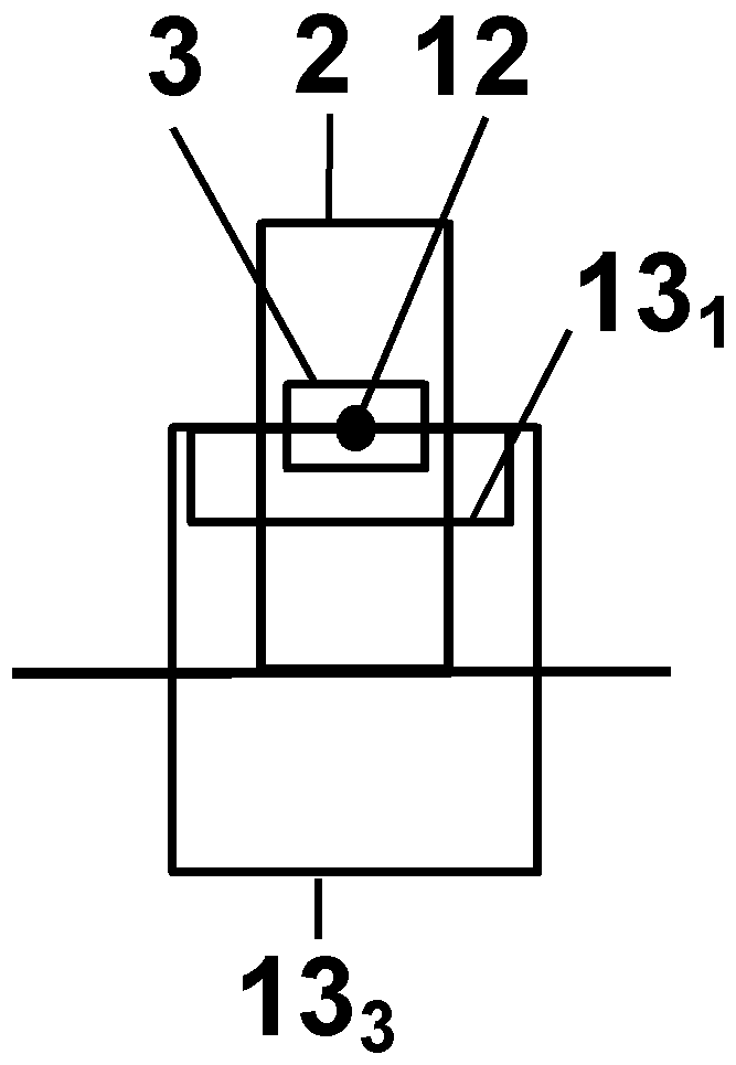
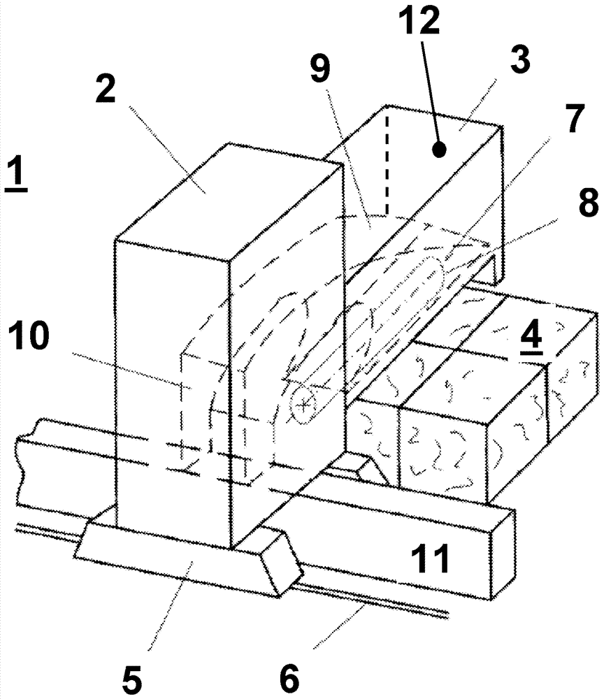
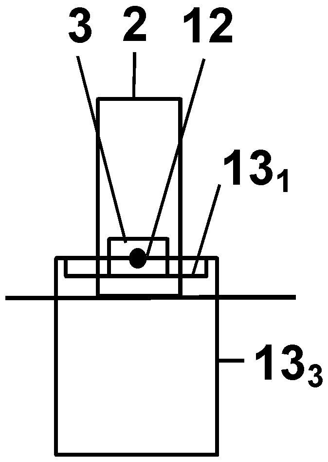
[0036] figure 1 A schematic diagram of a bag unpacking machine 1 according to the invention is shown. The bag unpacking machine 1 basically consists of a stripping tower 2 and a stripping element 3 . The stripping element 3 is mounted on one side of the stripping tower 2 and is arranged freely cantilevered over the fiber pack 4 . The stripping tower 2 is equipped with a traveling device 5 . The stripping tower 2 is moved on rails 6 along the fiber pack 4 with the help of the traveling device 5 . Due to this movement, the stripping element 3 mounted on the stripping tower 2 is guided on the surface of the fiber pack 4 located below it. The stripping element 3 mounted on the stripping tower 2 is designed to be height-adjustable, so that fiber bales 4 can be stripped continuously. A stripping roller 7 with a shaft 8 is arranged in the stripping element 3 . Stripping rolls 7 remove fiber bundles from the fiber bale 4 . The fiber bundle is removed from the stripping roll 7 by...


PUM


Abstract

The invention relates to a method for operating a bale opener (1) having a stripping element (3) and a safety device for protection against penetration into a hazardous zone of the stripping element (3), said safety device consisting of sensory safety means, wherein a monitoring region (13, 131, 132, 133) at the front beneath the stripping element is detected and wherein the stripping element (3) is mounted on a stripping tower (2). According to the invention the safety device is at least one two-dimensional laser scanner (12), on which at least one monitoring region (13, 131, 132, 133), which is adjustable and variable over time, is monitored. The invention also relates to a corresponding bale opener (1).

Description

technical field [0001] The invention relates to a method for operating a bale opener and a bale opener with a stripping element and means for preventing persons from entering the danger zone of the stripping element according to the preambles of the independent claims. safety equipment. Background technique [0002] It is known that, with machines in general and also with textile machines, the moving parts on the machine, especially the drive equipment, must be secured by safety devices to prevent anyone from getting too close. Since the drive part is arranged in a stationary mount with movable parts, usually a permanently mounted cover is sufficient. This can be designed so that the machine shuts off automatically when the cover is opened. [0003] In practice, several devices exist on textile machines, on so-called bale trimmers, to fix dangerous working elements. In the textile industry, especially in the preparation of spinning yarns, there are known machines for stri...

Claims


Application Information

Patent Timeline
Patent Type & Authority Applications(China)
IPC IPC(8): B65B69/00
CPCB65B69/00D01G7/06D01G31/00F16P3/144D01G7/14D01G7/04D01G7/10
Inventor G.格施里伊斯塞A.施米德
Owner MASCHINENFABRIK RIETER AG
Why Eureka
Try Eureka