
Toilet bowl flushing method

A toilet and waterway technology, which is applied in the field of toilet flushing, can solve the problems of difficulty in ensuring the flushing effect of the toilet, the effect is not good, and achieve the effects of improving the sewage discharge effect and ensuring the flushing effect.

Active Publication Date: 2017-10-27
XIAMEN R&T PLUMBING TECH
View PDF5 Cites 6 Cited by
  • Summary
  • Abstract
  • Description
  • Claims
  • Application Information

AI Technical Summary

Problems solved by technology

[0002] In the existing methods for flushing the toilet, most of them include the washing step of washing the surface of the toilet bowl and the spraying step of spraying the bottom of the toilet bowl, and most of them adopt a washing step and a spraying step, and some flushing steps use The washing step is carried out first, and then the spraying step is carried out, and the washing step and the spraying step are also carried out at the same time. Most of the toilets in the water tank use electromagnetic control valves to directly control the water supply to flush the toilet. Since the electromagnetic valve directly controls the water supply, the water pressure of the water supply source has a direct impact on the flushing effect of the toilet. Flushing steps In actual use, if the water pressure of the water supply source is high enough, the flushing effect of the toilet can still meet the requirements, but if the water pressure of the water supply source is low, it is difficult to ensure the flushing effect of the toilet, and the toilet often There will be residual dirt, the effect is not good

Method used


Image

  • Toilet bowl flushing method
  • Toilet bowl flushing method
  • Toilet bowl flushing method

Examples


Embodiment Construction

[0025] In order to illustrate the technical solutions of the embodiments of the present invention more clearly, the present invention will be further described below in conjunction with the accompanying drawings. The accompanying drawings in the following description are only some embodiments of the present invention. Under the premise of creative work, other drawings can also be obtained based on these drawings.

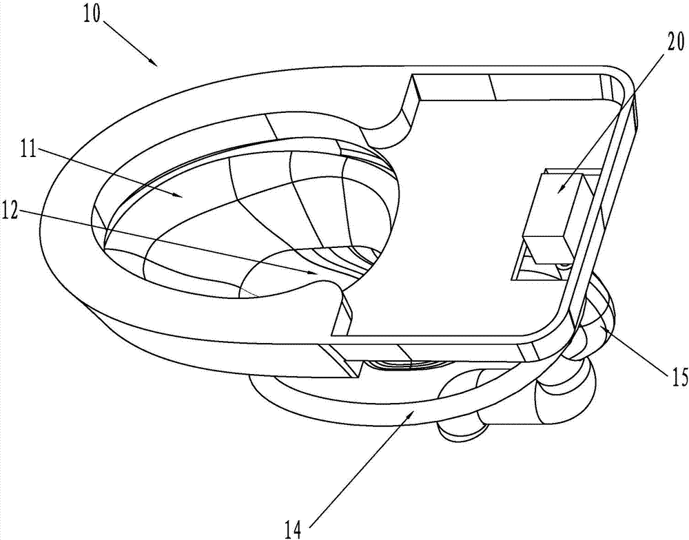
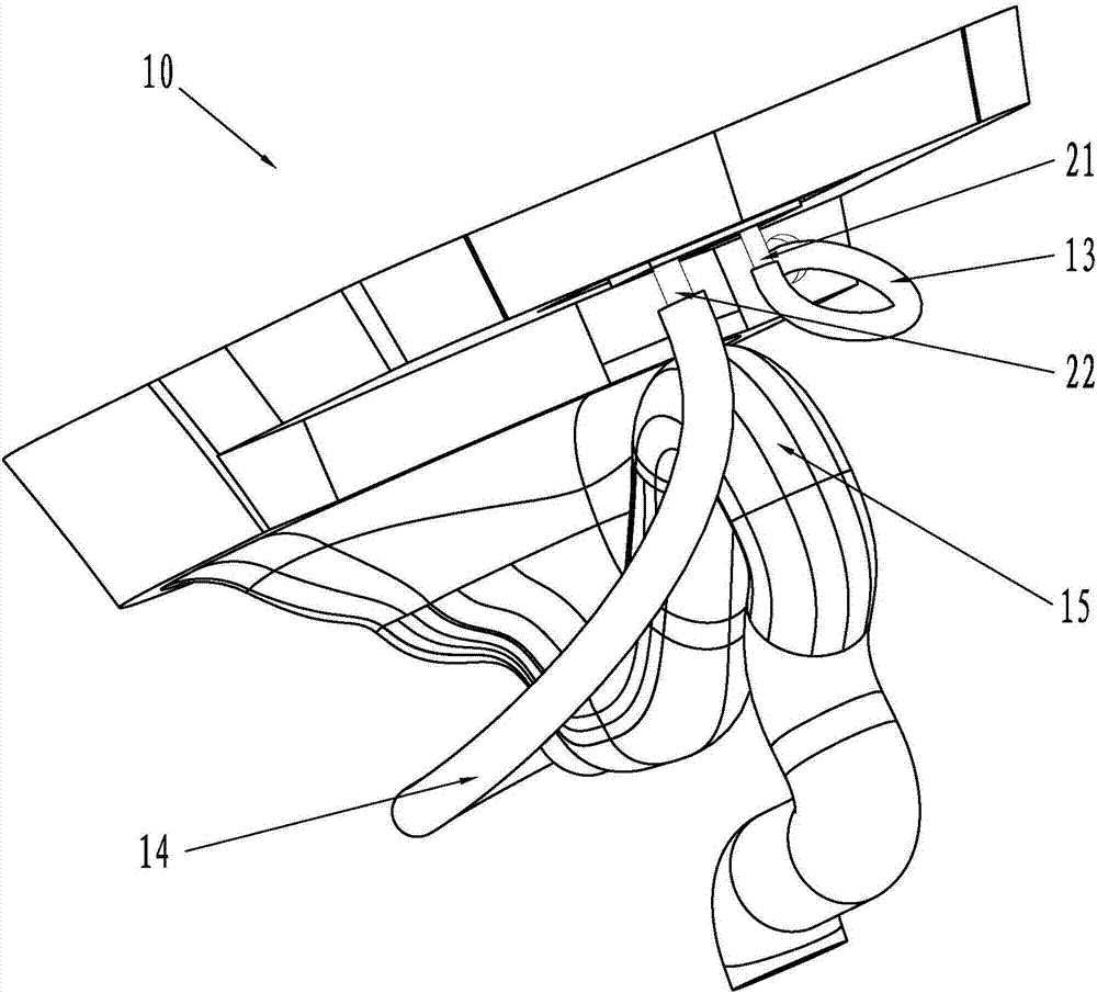
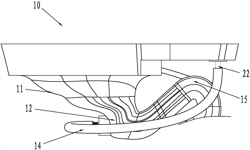
[0026] like Figure 1 to Figure 4 as shown, Figure 1 to Figure 4 A schematic diagram of the structure of the toilet for realizing the toilet flushing method of the present invention is shown. The toilet 10 is provided with a washing water channel 13 for washing the toilet bowl surface 11 and a spray water channel 14 for spraying the toilet bowl bottom 12 , and be provided with the sewage pipe 15 that is used for sewage discharge.

[0027] The flushing method of the present invention controls the water outlet of the scrubbing waterway 13 and the spraying waterway ...


PUM


Abstract

The invention relates to a toilet bowl flushing method. The method includes the steps of S1, allowing a control valve to open a jetting water path to allow the jetting water path to jet the bottom in a toilet bowl urinal so as to discharge dirt in the toilet bowl urinal out of a discharge pipe, and allowing the control valve to close the jetting water path after the jetting path is opened for a preset time period T1; S2, allowing the control valve to open a washing water path to allow the washing water path to wash the surface of the toilet bowl urinal so as to wash the dirt on the surface of the toilet bowl urinal to the bottom of the toilet bowl urinal, and allowing the control valve to close the washing water path after the washing water path is opened for a preset time period T2; S3, allowing the control valve to open the jetting water path again to allow the jetting water path to jet the bottom of the toilet bowl urinal to discharge the dirt in the toilet bowl urinal out of the discharge pipe again, and allowing the control valve to close the jetting water path after the jetting water path is opened again for a preset time period T3. The toilet bowl flushing method has the advantages that the hardware structure of an existing toilet bowl does not need to be changed, a toilet bowl can be effectively flushed by controlling the flushing steps of the toilet bowl, and an evident effect is achieved.

Description

technical field [0001] The invention relates to the technical field of toilets, in particular to a toilet flushing method. Background technique [0002] In the existing methods for flushing the toilet, most of them include the washing step of washing the surface of the toilet bowl and the spraying step of spraying the bottom of the toilet bowl, and most of them adopt a washing step and a spraying step, and some flushing steps use The washing step is carried out first, and then the spraying step is carried out, and the washing step and the spraying step are also carried out at the same time. Most of the toilets in the water tank use electromagnetic control valves to directly control the water supply to flush the toilet. Since the electromagnetic valve directly controls the water supply, the water pressure of the water supply source has a direct impact on the flushing effect of the toilet. Flushing steps In actual use, if the water pressure of the water supply source is high ...

Claims


Application Information

Patent Timeline
IPC IPC(8): E03D1/32E03D5/00
CPCE03D1/32E03D5/00
Inventor 陈海滨钟志军
Owner XIAMEN R&T PLUMBING TECH
Learn More