
Spring spinning mechanism

A spinning and indenter technology, applied in metal processing, metal processing equipment, manufacturing tools, etc., can solve problems such as unqualified pump body product quality, and achieve the effect of saving labor costs, ensuring product quality, and ensuring stability

Active Publication Date: 2017-11-03
BOZHON PRECISION IND TECH CO LTD
View PDF6 Cites 3 Cited by
  • Summary
  • Abstract
  • Description
  • Claims
  • Application Information

AI Technical Summary

Problems solved by technology

[0003] If the spring is assembled on the pump body, at this stage, the spring is generally placed manually in the spring hole of the pump body, and then the spring is introduced by the guide rod; the spring is a basic component with elastic characteristics, and the spring is not completely installed by the guide rod. In the spring hole of the pump body, the spring is compressed at the entrance of the spring buckle of the pump body. After the guide rod is away from the spring hole of the pump body, the spring pops out of the spring hole of the pump body, resulting in the lack of spring in the pump body and the product quality is unqualified.

Method used


Image

  • Spring spinning mechanism
  • Spring spinning mechanism
  • Spring spinning mechanism

Examples


Embodiment

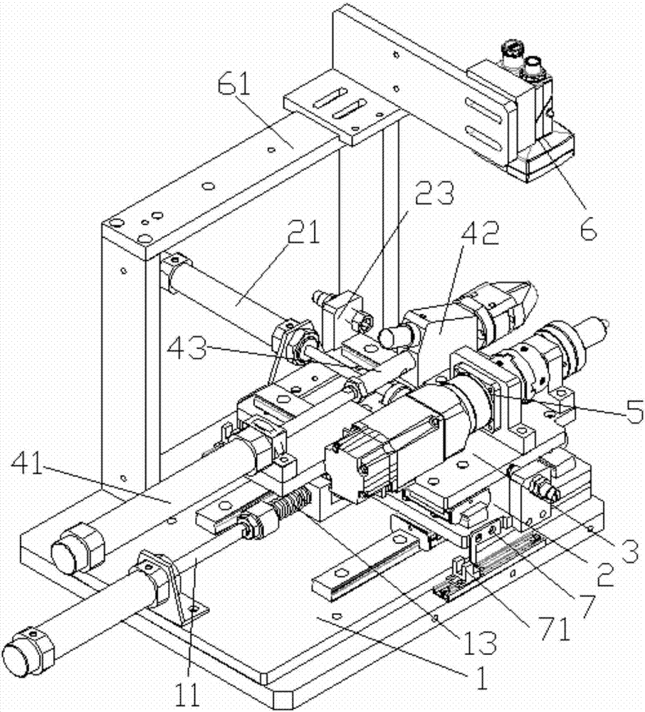
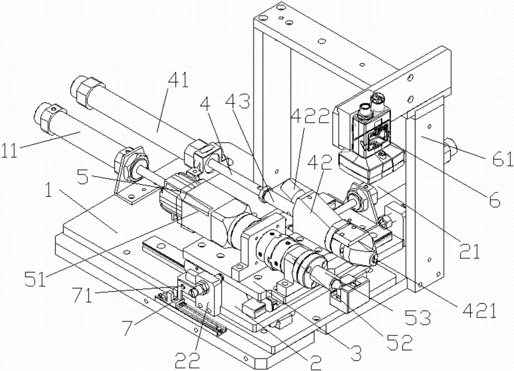
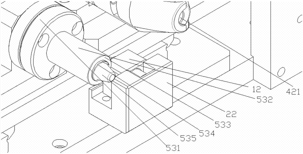
[0032] see Figure 1 to Figure 3 , this embodiment shows a spring spinning mechanism:

[0033] It includes a support plate 2 that can be slid back and forth on the bottom plate 1, a bearing plate 3 that can slide left and right on the support plate 2, a spring introduction assembly 4 and a spring spinning assembly 5 that are correspondingly installed on the support plate 3, and the passing inspection The installation frame 61 is arranged on the base plate 1 and cooperates with the spring introduction assembly 4 and the spring spinning assembly 5 to be used as a visual inspection device 6;

[0034] In this embodiment, the visual detection device 6 may be composed of a high-definition CDD detection camera;

[0035] The bottom plate 1 is provided with an induction device 7 composed of a grooved grating, and the support plate 2 is provided with an induction sheet 71 used in conjunction with the induction device 7, and the induction device 7 and the induction sheet 71 are used tog...


PUM


Abstract

The invention discloses a spring spinning mechanism. The spring spinning mechanism comprises a supporting plate, a bearing plate, a spring guide-in assembly, a spring spinning assembly and a visual detection device, wherein the supporting plate is arranged on a base plate in a front-back sliding mode, the bearing plate is arranged on the supporting plate in a left-right sliding mode, the spring guide-in assembly and the spring spinning assembly are arranged on the bearing plate in a corresponding mode, and the visual detection device is arranged on the base plate through a detection mounting frame and is coordinated with the spring guide-in assembly and the spring spinning assembly for use; a sensing device composed of a groove-shaped grating is arranged on the base plate; a sensor chip which is coordinated with the sensing device for use is arranged on the supporting plate; and the sensing device is coordinated with the sensor chip for use so as to form physical induction detection which is coordinated with a visual detection sensor for use. According to the spring spinning mechanism, the manual installation operation is simulated, springs can be automatically installed, labor cost can be saved, visual detection and physical detection are combined so that the stability for pinning the springs can be guaranteed, the springs can be ensured to be assembled in place, and therefore the product quality can be guaranteed.

Description

technical field [0001] The invention relates to the field of automation equipment, in particular to a spring spinning mechanism. Background technique [0002] In the process of modern production and assembly, there are problems to be solved in the assembly of some parts; [0003] If the spring is assembled on the pump body, at this stage, the spring is generally placed manually in the spring hole of the pump body, and then the spring is introduced by the guide rod; the spring is a basic component with elastic characteristics, and the spring is not completely installed by the guide rod. In the spring hole of the pump body, the spring is compressed at the inlet of the spring buckle of the pump body. After the guide rod is away from the spring hole of the pump body, the spring pops out of the spring hole of the pump body, resulting in the lack of spring in the pump body and the product quality is unqualified. [0004] Therefore, it is necessary to provide a spring spinning mec...

Claims


Application Information

Patent Timeline
Patent Type & Authority Applications(China)
IPC IPC(8): B23P19/027
CPCB23P19/027
Inventor 王金鱼王伟安宁黄浩明张国勇宋玉奇
Owner BOZHON PRECISION IND TECH CO LTD
Learn More