
Prefabrication device and prefabrication method of prefabricated beam shoe

A beam shoe and prefabricated platform technology, applied in the field of bridge engineering, can solve problems such as difficult inspection, wrong size, and large construction period, and achieve the effects of easy adjustment, smooth bottom surface, and good flatness.

Inactive Publication Date: 2017-11-03
CCCC ROAD & BRIDGE SPECIAL ENG
View PDF6 Cites 10 Cited by
  • Summary
  • Abstract
  • Description
  • Claims
  • Application Information

AI Technical Summary

Problems solved by technology

[0004] 1. It is inconvenient to adjust the thickness of the sand layer, the adjusted size is not completely accurate, and the size of different beam shoes needs to be adjusted repeatedly;
[0005] 2. The calculation of the thickness of the four corners of the beam shoe is relatively complicated and error-prone, and it is not as intuitive and reliable as the vertical and horizontal slope representation, which is not easy to check and review;
[0006] 3. The original beam shoe is covered by steel plates, steel bars, formwork, etc., which is not easy to check; if there is an error, the steel bars, formwork, etc. need to be removed, which is labor-intensive and time-consuming;
[0007] 4. The environment of the construction site is complex. Concrete slurry, curing water, oil and gas, etc. may cause local or overall subsidence of the sand layer, resulting in uneven bottom surfaces of beam boots or wrong vertical and horizontal slopes and dimensions. After the box girder is erected, the vertical and horizontal slopes do not meet the design requirements;
[0008] 5. The slope of the beam shoe cannot be checked and corrected in time: after the pouring is completed, the beam shoe is covered by the formwork, and the slope cannot be checked. Even if a problem is found, it is only when the beam body is erected, and the slope of the beam shoe cannot be corrected in time. It can stop the beam erection and wait for the processing of the wedge-shaped steel plate, which has a great impact on the construction period

Method used


Image

  • Prefabrication device and prefabrication method of prefabricated beam shoe
  • Prefabrication device and prefabrication method of prefabricated beam shoe
  • Prefabrication device and prefabrication method of prefabricated beam shoe

Examples


Embodiment Construction

[0040] In order to make the above objects, features and advantages of the present invention more comprehensible, specific implementations of the present invention will be described in detail below in conjunction with the accompanying drawings. Apparently, the described embodiments are only some, not all, embodiments of the present invention. Based on the implementation manners in the present invention, all other implementation manners obtained by persons of ordinary skill in the art without making creative efforts belong to the scope of protection of the present invention.

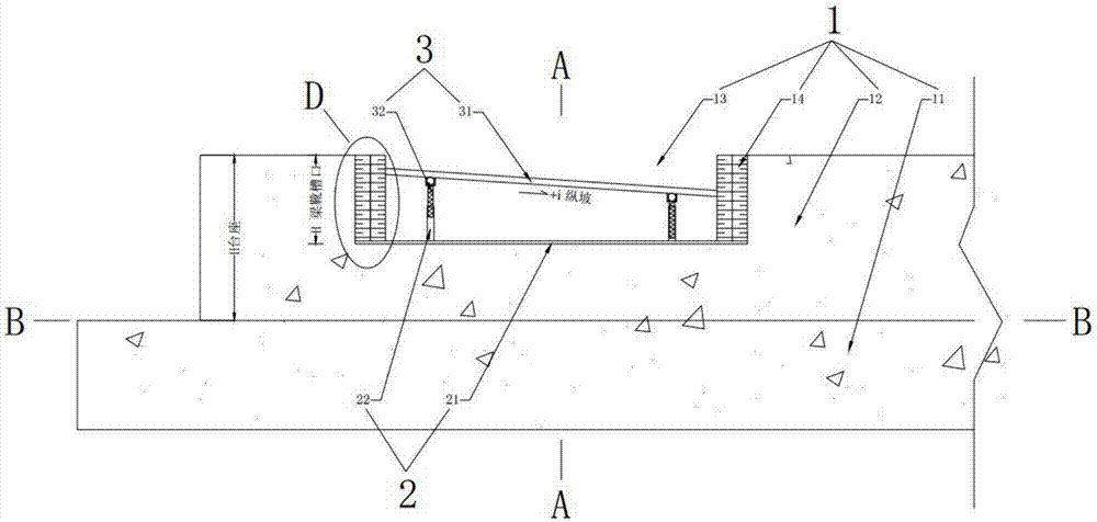
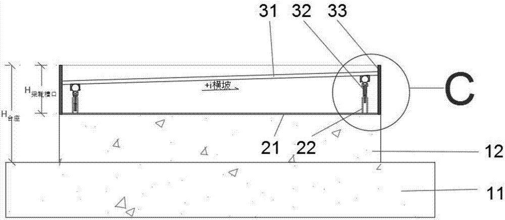
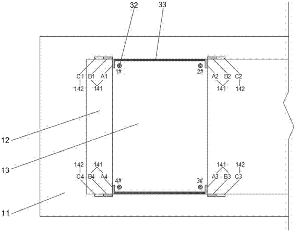
[0041] Such as figure 1 As shown, the general prefabrication method of the prefabricated beam shoe of the present invention and the corresponding formwork device include a prefabricated pedestal 1 , a fixing device 2 fixed to the bottom of the embedded notch of the prefabricated pedestal beam shoe, and an adjustable formwork device 3 .

[0042] Such as figure 1 As shown, the prefabricated pedestal 1 incl...


PUM


Abstract

The invention provides a prefabrication device and prefabrication method of a prefabricated beam shoe. The method is achieved through the device which is characterized in that ball head joint bearing screws welded at the four corners of the bottom surface of a steel template are connected with internal thread sleeves fixed to the bottom of a beam shoe embedding groove of a box beam prefabrication pedestal; and the ball head joint bearings can incline by any angle in all directions, so that when the ball head joint bearing screws at the four corners extend and retract up and down, the steel template and the top surface of the pedestal can be driven to form vertical and horizontal gradients and sizes which meet the requirement of the beam shoe. According to the device, manufacturing and mounting can be carried out at the same time during pedestal construction, the device is applicable to the beam shoes with different vertical and horizontal gradient and size requirements during box beam prefabrication, an adjustment method is convenient to implement, and the size is reliable.

Description

technical field [0001] The invention relates to the technical field of bridge engineering, in particular to a prefabrication device and a prefabrication method for prefabricated beam boots. Background technique [0002] With the development of my country's economic construction, the number and scale of bridges and other infrastructure projects have grown rapidly. Among them, prefabricated beam technology has been widely used in roads at all levels, Widely used in railway and other projects. [0003] Prefabricated beams are usually designed with a "positive tilting" design. The beam shoe is actually a wedge-shaped block at the bottom of the beam, mainly to ensure that the contact part between the beam body and the support is horizontal. Because the bottom surface of the beam has certain longitudinal and transverse slopes, direct contact with the support will cause the support to bear a large horizontal force and cause excessive shear, so a beam shoe is set above the support a...

Claims


Application Information

Patent Timeline
IPC IPC(8): B28B23/02B28B7/26E01D19/00
CPCB28B23/02B28B7/266E01D19/00
Inventor 陈胜王世祥赵东奎何波张英哲许鑫
Owner CCCC ROAD & BRIDGE SPECIAL ENG
Learn More