Concrete mixing equipment for hydraulic engineering construction

A technology for water conservancy projects and mixing equipment, applied in cement mixing equipment, clay preparation equipment, chemical instruments and methods, etc., can solve problems such as dust splashing, waste of manpower, uneconomical, etc., to reduce noise, speed up removal, and reduce investment Effect

Active Publication Date: 2017-11-03
临泉县三合商品混凝土有限公司
View PDF6 Cites 18 Cited by
  • Summary
  • Abstract
  • Description
  • Claims
  • Application Information

AI Technical Summary

Problems solved by technology

[0002] The construction of hydraulic engineering equipment is inseparable from the practicality of concrete. When concrete is in use, it needs to be mixed with water to meet the conditions for use. During the process of concrete mixing, dust is often splashed and pollutes the environment. Concrete mixers cannot realize automatic discharge, and manual operation is required to complete the discharge, which is time-consuming and laborious, and the concrete is easy to adhere to the inner wall of the mixing drum, resulting in waste of concrete and inconvenient cleaning; Insufficient mixing, long mixing time and other shortcomings directly lead to the failure of the mixed concrete to achieve the desired results. At the same time, the existing mixing equipment is inconvenient to move, locate, and has a lot of noise. It is easy to cause false coagulation due to excessive temperature, and most of the existing concrete mixing equipment is manually transported and fed, which is too wasteful of manpower and uneconomical. Therefore, a concrete mixing equipment for water conservancy construction is now needed. The shock device can move, the noise can be reduced by the sound-absorbing cover, the input of manual handling can be greatly reduced by the material transport device, the mixing can be made more fully by the auxiliary stirring device, and the concrete attached to the inner wall of the mixing drum can be removed by the scraping brush , through the cooling sheet, the temperature in the mixing drum can be reduced to prevent false coagulation; through the auxiliary discharge device, the removal of concrete can be accelerated; the amount of material entering can be controlled through the control plate

Method used


Image

  • Concrete mixing equipment for hydraulic engineering construction
  • Concrete mixing equipment for hydraulic engineering construction
  • Concrete mixing equipment for hydraulic engineering construction

Examples


Embodiment Construction

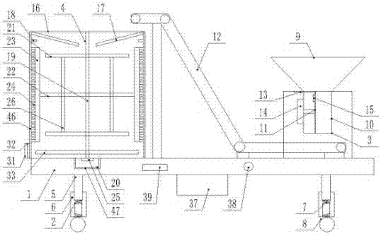
[0022] The present invention is specifically described below in conjunction with accompanying drawing, as Figure 1-6As shown, a concrete mixing equipment for water conservancy construction includes a basic rectangular bottom plate 1, the lower end of the basic rectangular bottom plate 1 is provided with a cushioning device 2, and the upper end is provided with a material delivery device 3 and a stirring device 4, and the cushioning device 2 is composed of the support feet 5 arranged at the four corners of the lower end surface of the basic rectangular bottom plate 1, the shock absorber 6 provided at the lower end of the support leg 5, the shock absorber spring 7 and the shock absorber 6 provided in the shock absorber 6 The moving wheel 8 that is provided with at the lower end is composed of, and the upper surface of the front end of the basic rectangular base plate 1 is provided with a material transport device 3, and the material transport device 3 is composed of a rectangula...


PUM


Abstract

The invention discloses concrete mixing equipment for hydraulic engineering construction. The concrete mixing equipment comprises a basic rectangular bottom plate. A cushioning device is arranged at the lower end of the basic rectangular bottom plate, a material transporting device and a mixing device are arranged at the upper end of the basic rectangular bottom plate, the cushioning device comprises supporting legs, a cushioning cylinder, a cushioning spring and movable wheels, the material transporting device comprises a rectangular holder, a feeding funnel, a feeding cylinder, a quantity control device and a large-inclination belt conveyor, the mixing device comprises a mixing cylinder, a feeding panel, a water inlet device, a rotating shaft, a first driving motor, a cross mixing rod, a cross support, a brush handle, a scraping and washing brush and an auxiliary mixing device, the auxiliary mixing device comprises an auxiliary mixing rod, a second driving motor and a spiral piece, a discharging port is formed in the side wall of the lower end of the mixing cylinder, and an auxiliary discharging device is arranged at the bottom of an inner cavity of the mixing cylinder. The concrete mixing equipment has the advantages of simple structure and high practicability.

Description

technical field [0001] The invention relates to the technical field of water conservancy construction equipment, in particular to concrete mixing equipment for water conservancy construction. Background technique [0002] The construction of hydraulic engineering equipment is inseparable from the practicality of concrete. When concrete is in use, it needs to be mixed with water to meet the conditions for use. During the process of concrete mixing, dust is often splashed and pollutes the environment. Concrete mixers cannot realize automatic discharge, and manual operation is required to complete the discharge, which is time-consuming and laborious, and the concrete is easy to adhere to the inner wall of the mixing drum, resulting in waste of concrete and inconvenient cleaning; Insufficient mixing, long mixing time and other shortcomings directly lead to the failure of the mixed concrete to achieve the desired results. At the same time, the existing mixing equipment is inconve...

Claims


Application Information

Patent Timeline
Patent Type & Authority Applications(China)
IPC IPC(8): B28C5/16
CPCB28C5/16
Inventor 不公告发明人
Owner 临泉县三合商品混凝土有限公司
Why Eureka
Try Eureka