Buoyancy water-lifting device for water conservancy and hydropower

A water conservancy, hydropower, and buoyancy technology, which is applied to the components of the pumping device for elastic fluids, the liquid variable-capacity machinery, and the variable-capacity pump components, etc. The effect of saving water resources, facilitating collection and saving materials

Inactive Publication Date: 2017-11-03
安徽诺鑫自动化设备有限公司
View PDF5 Cites 0 Cited by
  • Summary
  • Abstract
  • Description
  • Claims
  • Application Information

AI Technical Summary

Problems solved by technology

Students majoring in water conservancy and hydropower engineering mainly study the basic theories and basic knowledge of mathematics, mechanics and building structures necessary for the construction of water conservancy and hydropower projects, so that students can get the necessary basic training in engineering design methods, construction management methods and scientific research methods, with Basic capabilities in surveying, planning, design, construction, scientific research and management of water conservancy and hydropower projects. Water conservancy and hydropower is the basic industry for national economic and social development. It plays a vital role in people's production and life. With the development of science and technology Most of the water lifting devices currently used are realized by using electric energy or mechanical energy. Although this method replaces manpower and saves time, it still has disadvantages such as high energy consumption, low efficiency, and environmental protection.

Method used


Image

  • Buoyancy water-lifting device for water conservancy and hydropower
  • Buoyancy water-lifting device for water conservancy and hydropower
  • Buoyancy water-lifting device for water conservancy and hydropower

Examples


Embodiment Construction

[0018] The following will clearly and completely describe the technical solutions in the embodiments of the present invention with reference to the accompanying drawings in the embodiments of the present invention. Obviously, the described embodiments are only some, not all, embodiments of the present invention. Based on the embodiments of the present invention, all other embodiments obtained by persons of ordinary skill in the art without making creative efforts belong to the protection scope of the present invention.

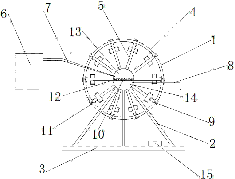
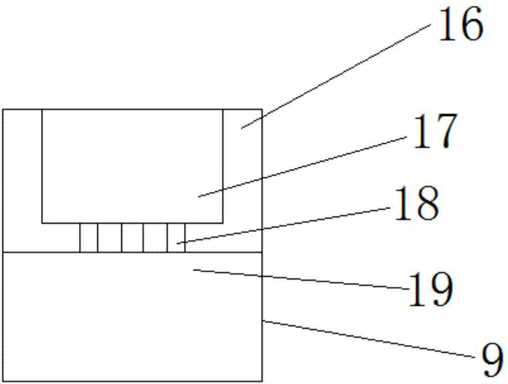
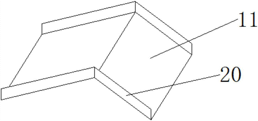
[0019] see Figure 1-3 , the present invention provides a technical solution: a buoyancy water lifting device for water conservancy and hydropower, comprising a water wheel 1, a bracket 2, a base 3, a fixed frame 4, an inflatable tube 5, an air supply device 6, an air guide tube 7, an exhaust Pipe 8, water lifting mechanism 9, Y355 motor 10, water dividing plate 11, fixed plate 12, inflatable chamber 13, exhaust chamber 14, programmable logic controller 15, wa...


PUM


Abstract

The invention discloses a buoyancy water lifting device for water conservancy and hydropower. The middle part of the waterwheel is provided with a Y355 motor, the outer side of the Y355 motor is provided with a fixed plate, the top of the fixed plate is provided with an inflatable chamber, and the inside of the inflatable chamber is provided with an air duct. One end of the air guide tube is provided with an air supply device, the bottom of the fixed plate is provided with an exhaust chamber, the inside of the exhaust chamber is provided with an exhaust pipe, the outside of the inflatable chamber and the exhaust chamber is provided with an inflatable pipe, and one end of the inflatable pipe is provided There is a fixed frame, one side of the fixed frame is provided with a water lifting mechanism, the middle part of the top of the water lifting mechanism is provided with a protrusion, the two sides of the protrusion are provided with a water container, the bottom of the protrusion is provided with a through hole, and the through hole The bottom is provided with an airbag, the bottom of the waterwheel is provided with a bracket, the bottom of the bracket is provided with a base, the surface of the base is provided with a programmable controller, and the bottom of the through hole of the present invention is provided with an airbag, which can be inflated when the gas is fed into it. The water lifting mechanism generates buoyancy and drives the waterwheel to run.

Description

technical field [0001] The invention relates to the technical field of water-lifting devices for water conservancy and hydropower, in particular to a buoyancy water-lifting device for water conservancy and hydropower. Background technique [0002] Water Conservancy and Hydropower Engineering Cultivate senior engineering and technical personnel who have the knowledge of surveying, planning, design, construction, scientific research and management of water conservancy and hydropower projects, and can be engaged in planning, design, construction, scientific research and management in water conservancy, hydropower and other departments . Students majoring in water conservancy and hydropower engineering mainly study the basic theories and basic knowledge of mathematics, mechanics and building structures necessary for the construction of water conservancy and hydropower projects, so that students can get the necessary basic training in engineering design methods, construction mana...

Claims


Application Information

Patent Timeline
Patent Type & Authority Applications(China)
IPC IPC(8): F04B19/10F04B17/00F04B53/00
CPCF04B19/10F04B17/00F04B53/00
Inventor 章军
Owner 安徽诺鑫自动化设备有限公司
Why Eureka
Try Eureka