Dead-time compensation method and device of inverter and inverter
A dead zone compensation and inverter technology, applied in the direction of output power conversion device, AC power input conversion to DC power output, electrical components, etc., can solve torque ripple, output phase voltage and current waveform distortion, out of step etc. to achieve the effect of reducing drive power consumption and improving drive efficiency
- Summary
- Abstract
- Description
- Claims
- Application Information
AI Technical Summary
Problems solved by technology
Method used
Image

Examples
Embodiment Construction
[0054] The technical solutions of the present invention will be described in further detail below with reference to the accompanying drawings and embodiments.
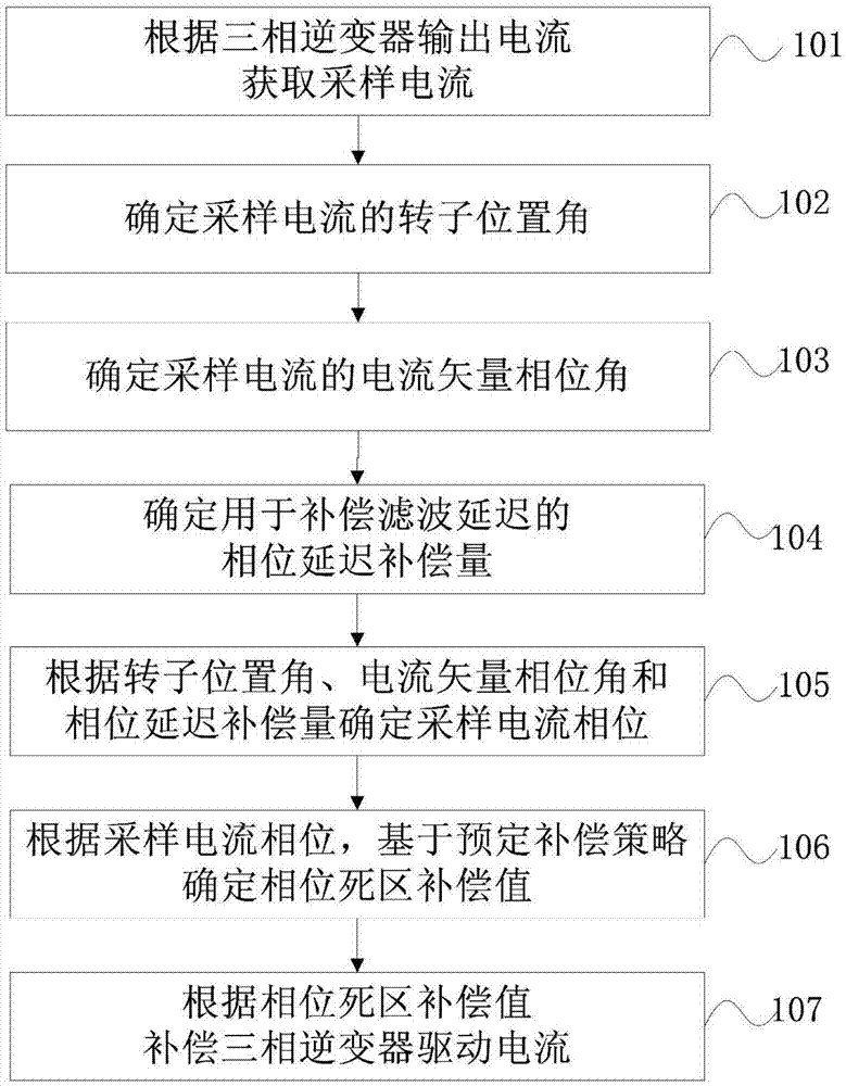
[0055] The flow chart of an embodiment of the inverter dead zone compensation method of the present invention is as follows figure 1 shown.
[0056] In step 101, the output current of the three-phase inverter is collected to obtain a sampled current.
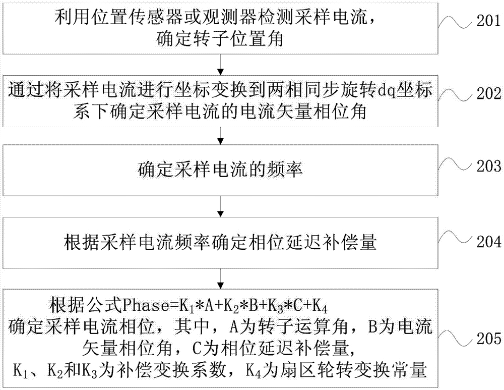
[0057] In step 102, the rotor position angle is determined according to the sampled current, for example, the rotor position angle is calculated using an arctangent function.
[0058] In step 103, the current vector phase angle is determined according to the sampled current. In one embodiment, the current vector phase angle of the sampling current can be determined by transforming the sampling current into a two-phase synchronously rotating dq coordinate system. In one embodiment, the coordinate transformation of the sampling current is first carried out into the two-...
PUM
 Abstract
Description
Claims
Application Information
 - R&D Engineer
- R&D Manager
- IP Professional
- Industry Leading Data Capabilities
- Powerful AI technology
- Patent DNA Extraction
Browse by: Latest US Patents, China's latest patents, Technical Efficacy Thesaurus, Application Domain, Technology Topic.
© 2024 PatSnap. All rights reserved.Legal|Privacy policy|Modern Slavery Act Transparency Statement|Sitemap