
Combined type piezoelectric electric generator

A generator and combined technology, applied in the direction of generator/motor, piezoelectric effect/electrostrictive or magnetostrictive motor, electrical components, etc., can solve the problems of low reliability and poor environmental adaptability, and achieve reliable High performance, strong power generation and power supply capabilities

Pending Publication Date: 2017-11-03
ZHEJIANG NORMAL UNIVERSITY
View PDF4 Cites 0 Cited by
  • Summary
  • Abstract
  • Description
  • Claims
  • Application Information

AI Technical Summary

Problems solved by technology

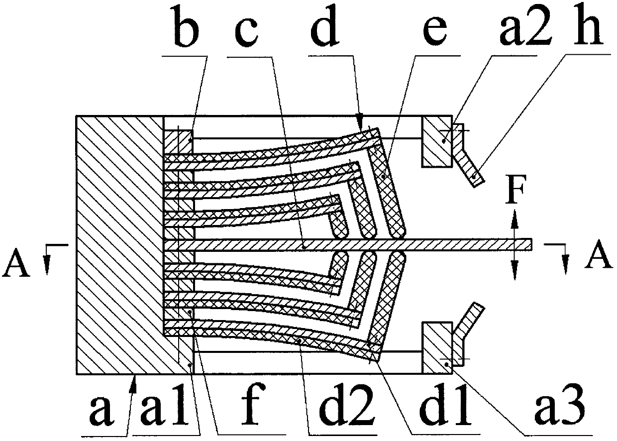
[0003] In view of the disadvantages of existing piezoelectric generators such as low reliability and poor environmental adaptability caused by bidirectional bending deformation of a single piezoelectric vibrator, the present invention proposes a combined piezoelectric generator. The implementation scheme adopted in the present invention is: There are lug plates, upper limit frames and lower limit frames, buffer reeds are installed on the upper limit frame and lower limit frames through screws, and excitation reeds and piezoelectric vibrators are installed on the ear plates through screws and pressure blocks. The number of piezoelectric vibrators on the side is equal, and gaskets are crimped between the exciting reed and its adjacent piezoelectric vibrators, and between two adjacent piezoelectric vibrators; the piezoelectric vibrators are bonded by the substrate and the piezoelectric sheet. The free end of the piezoelectric vibrator is installed with a top block through screws, the top block is installed on one side of the substrate, the free end of the top block leans against the excitation reed, and the top blocks on both sides of the excitation reed are symmetrically arranged

Method used


Image

  • Combined type piezoelectric electric generator
  • Combined type piezoelectric electric generator

Examples


Embodiment Construction

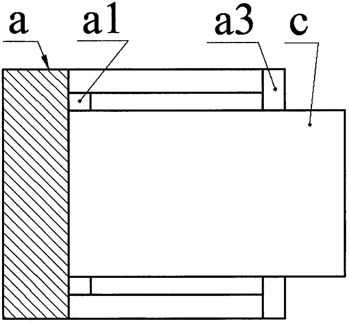
[0010] The base a is provided with an ear plate a1, an upper limit frame a2 and a lower limit frame a3, the upper limit frame a2 and the lower limit frame a3 are equipped with a buffer reed h via screws, and the ear plate a1 is installed with a screw and a pressure block b. Excite reed c and piezoelectric vibrator d, the number of piezoelectric vibrators d on both sides of exciting reed c is equal, between exciting reed c and its adjacent piezoelectric vibrator d, and between two adjacent piezoelectric vibrators d A spacer f is crimped between them; the piezoelectric vibrator d is formed by bonding the substrate d1 and the piezoelectric sheet d2, and the free end of the piezoelectric vibrator d is installed with a top block e via a screw, and the top block e is installed on one side of the substrate d1. On the side, the free end of the top block e leans against the excitation reed c, and the top blocks e on both sides of the excitation reed c are arranged symmetrically.

[001...


PUM


Abstract

The invention relates to a combined type piezoelectric electric generator and belongs to the field of piezoelectric electricity generation. Buffering reeds are mounted on upper and lower limiting frames of a pedestal, excitation reeds and piezoelectric vibrators are mounted on ear plates of the pedestal, the piezoelectric vibrators are formed by bonding substrates and piezoelectric sheets, butting blocks mounted on free ends of the piezoelectric vibrators are butted against the excitation reeds, and each of the piezoelectric vibrators is of a flat and straight structure before installation and is of a bent structure after installation; during work, maximum compressive stress on the piezoelectric sheets is half of permissible compressive stress, the piezoelectric vibrators on upper sides and lower sides of the excitation reeds are the same in deformation and stress state, the excitation reeds are not bent or deformed, and free ends of the excitation reeds contact the buffering reeds before gradually contacting the upper limiting frame or the lower limiting frame when external force is large. Advantageous characteristics of the combined type piezoelectric electric generator are that the piezoelectric sheets are only under the compressive stress, a buffering and limiting mechanism is adopted, high reliability can be realized, the piezoelectric electric generator is suitable for high-intensity and large-amplitude vibration, a plurality of the piezoelectric vibrators are excited synchronously via the excitation reeds, and strong electricity generation and power supply capacity can be realized.

Description

technical field [0001] The invention belongs to the technical field of piezoelectric power generation and energy recovery, and in particular relates to a combined piezoelectric generator. Background technique [0002] The use of the positive piezoelectric effect of piezoelectric materials to collect environmental energy for power generation and the construction of micro energy harvesters or piezoelectric generators has become a hot spot at home and abroad. Its purpose is to replace batteries for remote sensing, implanted monitoring systems and portable Powering micropower electronics. At present, there are more than 10 kinds of environmental energy that can be effectively recovered by using piezoelectric materials, among which there are more researches: environmental vibration energy, rotational kinetic energy of machine tools, vehicles, engines and generator shafts and bearings, human limbs and organs Motion energy, fluid energy such as waves, wind, rivers, etc. Although ...

Claims


Application Information

Patent Timeline
IPC IPC(8): H02N2/18
CPCH02N2/186
Inventor 马继杰费翔阚君武
Owner ZHEJIANG NORMAL UNIVERSITY
Learn More