Supercharge Your Innovation With Domain-Expert AI Agents!

Digital motor power saver

A technology for electric motors and power savers, which is applied in the direction of motor generator control, electrical components, power factor control, etc., and can solve problems such as unbalanced three-phase terminal voltage, easy drift of capacitance value, and influence on operating performance

Active Publication Date: 2017-11-03
浙江勇圣智能科技有限公司
View PDF7 Cites 0 Cited by
  • Summary
  • Abstract
  • Description
  • Claims
  • Application Information

AI Technical Summary

Problems solved by technology

[0002] When the load of the motor is low, the efficiency of the motor will decrease, that is, the so-called large horse-drawn cart, usually by reducing the terminal voltage of the motor to reduce the iron loss of the motor and improve the operating efficiency of the motor; by adjusting the motor connected in series The conduction angle of the bidirectional thyristor can adjust the terminal voltage of the motor; the circuit that controls the conduction angle of the thyristor includes a unijunction transistor trigger circuit and a sawtooth wave phase-shift trigger circuit. The common point of these circuits is that they use capacitors to delay time (phase shift); for a three-phase motor, a trigger circuit must be set for each phase, and the capacitors in it must be matched precisely, so that the conduction angles of the three triacs can be consistent, otherwise the three-phase terminal voltage of the motor will be different. balance, which affects its operating performance; a common problem is that the capacitance value is prone to drift, making the conduction angles of the three triacs inconsistent

Method used


Image

  • Digital motor power saver
  • Digital motor power saver

Examples


Embodiment Construction

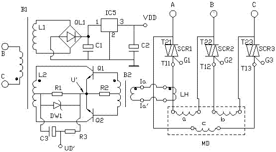
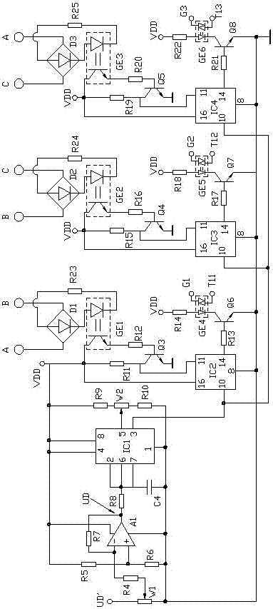
[0008] The specific embodiment of the present invention will now be described in conjunction with the accompanying drawings.

[0009] A digital motor saver, which includes three bidirectional thyristors connected in series between the windings of a three-phase motor MD and the mains, wherein the first bidirectional thyristor is controlled by the first trigger control circuit, the second The bidirectional thyristor is controlled by the second trigger control circuit, and the third bidirectional thyristor is controlled by the third trigger control circuit. It is characterized in that each trigger control circuit has the same circuit structure, which includes a counter and a synchronous pulse acquisition circuit. , flip-flop; the counting pulse input to the counter in each trigger control circuit comes to a voltage-controlled oscillator, and when the control voltage of the voltage-controlled oscillator control terminal changes, the counting pulse frequency of its output changes ac...


PUM


Abstract

Provided is a digital motor power saver, comprising three two-way silicon controlled rectifiers connected to a winding of a three-phase motor in series. Each two-way silicon controlled rectifiers is controlled by a corresponding trigger control circuit. Each trigger control circuit has the same circuit structure, and comprises a counter, a synchronization pulse acquisition circuit and a trigger, wherein a count pulse of the counter comes from a voltage-controlled oscillator, when the voltage of a control end of the voltage-controlled oscillator is changed, a count pulse frequency output therefrom is changed accordingly, a synchronization pulse appears when the corresponding line voltage is zero-crossing, when the synchronization pulse appears, an output end of the counter is low-level, after the synchronization pulse disappears, the counter starts counting, and when a count given by the counter reaches a specified value, the output end of the counter is high-level, so that the trigger drives the corresponding two-way silicon controlled rectifier to be switched on. The control voltage of the control end of the voltage-controlled oscillator comes from a phase voltage signal output by a phase detector, and when a power factor of the motor is reduced, the terminal voltage of the motor is reduced, thereby maintaining the power factor to be within an appropriate range.

Description

technical field [0001] The invention relates to a motor saver, which improves the power factor when the motor is running by adjusting the terminal voltage of the motor to reduce the iron loss of the motor. Background technique [0002] When the load of the motor is low, the efficiency of the motor will decrease, that is, the so-called large horse-drawn cart, usually by reducing the terminal voltage of the motor to reduce the iron loss of the motor and improve the operating efficiency of the motor; by adjusting the motor connected in series The conduction angle of the bidirectional thyristor can adjust the terminal voltage of the motor; the circuit that controls the conduction angle of the thyristor includes a unijunction transistor trigger circuit and a sawtooth wave phase-shift trigger circuit. The common point of these circuits is that they use capacitors to delay time (phase shift); for a three-phase motor, a trigger circuit must be set for each phase, and the capacitors ...

Claims


Application Information

Patent Timeline
Patent Type & Authority Applications(China)
IPC IPC(8): H02P23/26
CPCH02P23/26H02P2201/15
Inventor 高玉琴
Owner 浙江勇圣智能科技有限公司
Features
  • R&D
  • Intellectual Property
  • Life Sciences
  • Materials
  • Tech Scout
  • Unparalleled Data Quality
  • Higher Quality Content
  • 60% Fewer Hallucinations
Learn More