Tooth-claw type crusher

A pulverizer and claw technology, applied in the field of feed processing, can solve the problems of high power consumption, low work efficiency, and easy spontaneous combustion, etc., and achieve the effects of long service life, improved crushing efficiency, and good space utilization

Inactive Publication Date: 2017-11-07
SHANDONG ACADEMY OF AGRI MACHINERY SCI
View PDF11 Cites 1 Cited by
  • Summary
  • Abstract
  • Description
  • Claims
  • Application Information

AI Technical Summary

Problems solved by technology

Driven by the claws or hammers, the material can easily form a powder circulation layer on the surface of the screen. Under the action of centrifugal force, large particles in the material will accumulate on the periphery of the circulation layer under the action of centrifugal force, while small particles of material will It is easy to accumulate in the inner side of the circulation layer, and the large-grained materials block the small-grained materials from passing through the screen, resulting in the blocking of the materials, so that the products with qualified particle sizes cannot be discharged in time, which will inevitably lead to over-crushing, wasting time and effort. Electricity, there are problems of large power consumption and low work efficiency, and the temperature of the material rises, and it is prone to spontaneous combustion, causing accidents
At the same time, the traditional claw-type pulverizer still has uneven distribution of materials on both sides of the rotor disk, and it is difficult for materials to enter the inner working area after entering the pulverization chamber, which reduces the pulverization efficiency of the unit.

Method used


Image

  • Tooth-claw type crusher
  • Tooth-claw type crusher
  • Tooth-claw type crusher

Examples


Embodiment Construction

[0028] Attached below figure 1 to attach Figure 4 The present invention will be further described.

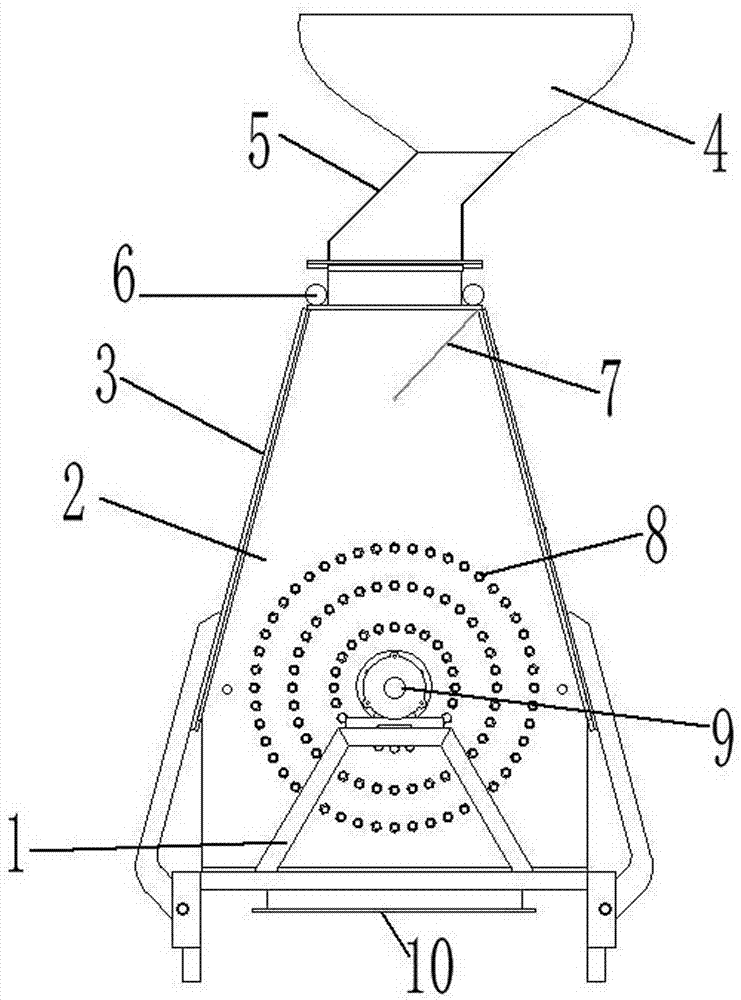
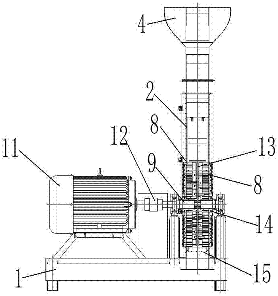
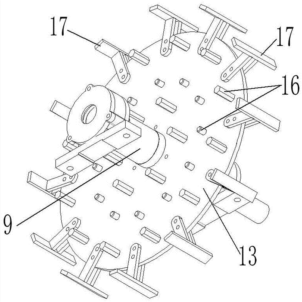
[0029] A claw-type pulverizer, comprising: a machine base 1; a casing 2, which is installed on the machine base 1, and is provided with a closed cavity inside, and the upper end of the casing 2 is provided with a feed port 18 connected to the cavity, The lower end is provided with a discharge port 10 connected to the cavity; the feed hopper 4 is installed on the casing 2, and its lower end is connected with the feed port 18; The longitudinal rotation is installed in the cavity inside the housing 2; the motor 11 is installed on the machine base 1, and its output shaft is connected with a main shaft 9 through a coupling 12; several claws II 16, and the rotor disk 13 or so The claws II 16 at both ends are arranged on the end face of the rotor disk 13 in the form of M concentric circles, M is a natural number greater than or equal to 2; a number of claws I 8, each claw on the in...


PUM


Abstract

A tooth-claw type crusher comprises a machine base, a machine case, a feed hopper, a motor, a plurality of tooth claws II, a plurality of tooth claws I, flat tooth ends and a screening plate. A circulation layer is destroyed through a containing cavity in the machine case. The motion direction of large-particle materials moving in a manner of attaching to the screening plate is changed. Fine powder with the qualified particle size falls into a discharge port through the screening plate so that the fine powder with the qualified particle size can be transferred out in time. The condition of over-crushing is effectively avoided. The problems of large power consumption and low working efficiency caused due to the fact that products with the qualified particle size cannot be discharged of a feed grinder in time in the prior art are solved. As the screening plate is of a raindrop-shaped structure, the design of a raindrop-shaped crushing chamber can be adopted for a cavity, the circulation layer formed by materials during rotating can be destroyed, and the materials can make full contact with the tooth claws and the flat teeth. Moreover, materials on the two sides of a rotor disk are uniform, secondary crushing is achieved really, and the crushing efficiency is greatly improved.

Description

technical field [0001] The invention relates to the field of feed processing, in particular to a claw-type pulverizer. Background technique [0002] There are many types of feed mills. As far as the current market is concerned, the commonly used grinders are claw and hammer grinders. Driven by the claws or hammers, the material can easily form a powder circulation layer on the surface of the screen. Under the action of centrifugal force, large particles in the material will accumulate on the periphery of the circulation layer under the action of centrifugal force, while small particles of material will It is easy to accumulate in the inner side of the circulation layer, and the large-grained materials block the small-grained materials from passing through the screen, resulting in the blocking of the materials, so that the products with qualified particle sizes cannot be discharged in time, which will inevitably lead to over-crushing, wasting time and effort. Electricity has...

Claims


Application Information

Patent Timeline
Patent Type & Authority Applications(China)
IPC IPC(8): B02C13/13B02C13/282B02C13/286B02C23/18
CPCB02C13/13B02C13/282B02C13/286B02C23/18B02C2013/28618
Inventor 崔相全李寒松赵峰郭大勇孔凡祝张宗超慈文亮贾振超贺晓东武文璇
Owner SHANDONG ACADEMY OF AGRI MACHINERY SCI
Why Eureka
Try Eureka