Method for machining valve guide pipe hole and valve base ring hole through horizontal milling machine

A valve guide, milling machine processing technology, applied in milling machine equipment, milling machine equipment details, metal processing equipment and other directions, can solve the problem that the processing method cannot meet the requirements, increase the research cost, and it is difficult that the cylinder head valve guide hole and the valve seat ring are coaxial To solve the problems such as degree, to achieve the effect of simple and convenient processing technology, low cost and high precision

Inactive Publication Date: 2017-11-07
CHONGQING UNIV OF TECH
View PDF1 Cites 1 Cited by
  • Summary
  • Abstract
  • Description
  • Claims
  • Application Information

AI Technical Summary

Problems solved by technology

[0002] Usually, for the processing of the valve guide hole and valve seat ring on the cylinder head for scientific research trial production and small batch production, because its structure and size have not been fully finalized, the axis of the cylinder head valve guide hole and valve seat ring is not in line with the bottom surface of the cylinder head. Vertical, but at a certain angle with the bottom surface of the cylinder head, the general processing method cannot meet the requirements
If special-purpose machine tools or machining centers are used for processing, although the processing requirements can be met, corresponding equipment must be purchased, which undoubtedly increases research costs for scientific research and trial production.
However, if ordinary machine tools are used for processing, different datums need to be used to position the cylinder head multiple times, and it is difficult to ensure the coaxiality of the cylinder head valve guide hole and the valve seat ring, as well as the cylindricity and straightness of the valve guide hole

Method used


Image

  • Method for machining valve guide pipe hole and valve base ring hole through horizontal milling machine

Examples


Embodiment Construction

[0020] The present invention will be further described in detail below in conjunction with the accompanying drawings.

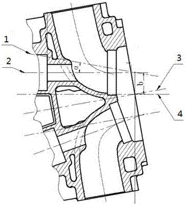
[0021] Such as figure 1 As shown, reference numeral 1 is the centerline of the valve guide hole before rotation, reference numeral 2 is the centerline of the valve guide hole after rotation, reference numeral 3 is the centerline of the cylinder head after rotation, and reference numeral 4 is the cylinder head before rotation center line.

[0022] The method for processing the valve guide hole and the valve seat ring hole by a horizontal milling machine in this specific embodiment includes the following steps:

[0023] 1) Place the cylinder head horizontally on the machine tool workbench, make the side of the valve guide hole to be processed face the machine tool spindle, align the center point of the cylinder head, move the machine tool spindle so that the center line of the machine tool spindle is coaxial with the center line of the cylinder head, Then cle...


PUM


Abstract

The invention discloses a method for machining a valve guide pipe hole and a valve base ring hole through a horizontal milling machine. A one-time positioning method is adopted, a cylinder cover is overturned by 90 degrees, and the axis of the valve guide pipe hole and the axis of the valve base ring hole are made to be parallel with a workbench face; then the workbench face is rotated; in this way, a machine tool main shaft can be aligned with the axis of the valve guide pipe hole and the axis of the valve base ring hole; and then by means of a bottom hole drilling process, a coarse broaching process, a finish broaching process and a finish milling process, the position precision, the size precision, the cylindricity, the straightness and the like of the valve guide pipe hole are guaranteed. The machining process is simple and convenient, precision is high, cost is low, and a good technological effect can be achieved without a special machine tool.

Description

technical field [0001] The invention relates to the field of machining, in particular to a method for machining valve guide holes and valve seat ring holes by using a horizontal milling machine. Background technique [0002] Usually, for the processing of the valve guide hole and valve seat ring on the cylinder head for scientific research and trial production and small batch production, because its structure and size have not been fully finalized, the axes of the cylinder head valve guide hole and valve seat ring are not in line with the bottom surface of the cylinder head. Vertical, but a certain angle with the bottom surface of the cylinder head, the general processing method can not meet the requirements. If special-purpose machine tools or machining centers are used for processing, although the processing requirements can be met, corresponding equipment must be purchased, which undoubtedly increases research costs for scientific research and trial production. However, ...

Claims


Application Information

Patent Timeline
Patent Type & Authority Applications(China)
IPC IPC(8): B23P15/00B23C3/00
CPCB23P15/00B23C3/00F15B15/08
Inventor 张勇杨靖杨秀林李朝晖冯仁华
Owner CHONGQING UNIV OF TECH
Why Eureka
Try Eureka