Equal-tooth adjustment positioning device for iron plate of metal decorating machine

A technology for adjusting positioning and iron printing machines, applied to printing machines, general parts of printing machinery, printing, etc., can solve the problems of increasing machine debugging time and labor intensity, wasting iron sheets, etc., and achieve shortening overprinting time, improving work efficiency, and displacement Speed ​​and position control for flexible effects

Active Publication Date: 2017-11-07
SHANGHAI RUIYUAN PRINTING EQUIP
View PDF8 Cites 0 Cited by
  • Summary
  • Abstract
  • Description
  • Claims
  • Application Information

AI Technical Summary

Problems solved by technology

[0005]In the process of adjusting the position of the front gauge, it is generally necessary to manually adjust the screw to move the front and rear positions of the front gauge, and each machine owner must manually fine-tune In the end, the accuracy of the iron plate overprinting can meet the requirements, which undoubtedly increases the debugging time and labor intensity of the technicians to a large extent, and also wastes a lot of time for trial printing due to the adjustment of the registration. iron sheet

Method used


Image

  • Equal-tooth adjustment positioning device for iron plate of metal decorating machine
  • Equal-tooth adjustment positioning device for iron plate of metal decorating machine
  • Equal-tooth adjustment positioning device for iron plate of metal decorating machine

Examples


Embodiment Construction

[0041] The present invention will be further described below in conjunction with the accompanying drawings.

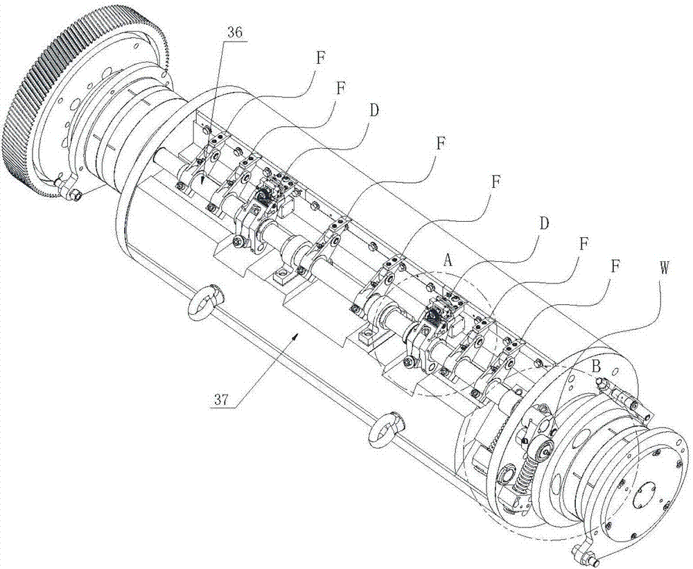
[0042] see figure 1 with figure 2 , with reference to Figure 3-10 , the figure shows a kind of tooth adjustment and positioning device for iron plate of iron printing machine related to the present invention, and the key technical solution adopted by it is:

[0043] The tooth adjusting and positioning device includes a toothing shaft 36 movable on the inside of the outer edge of the two axial ends of the impression cylinder 37. On the toothing shaft 36, there are several pairs of auxiliary toothing positioning mechanisms F arranged at intervals in the axial direction. A first-class tooth electric adjustment and positioning mechanism D is positioned on the teeth-grinding shaft 36 between the auxiliary teeth-grinding mechanisms F.

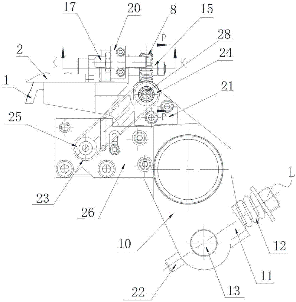
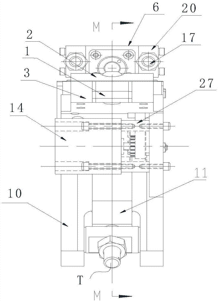
[0044] Such as Figure 2-7 As shown, the equal-tooth electric adjustment and positioning mechanism D includes a front gauge seat 10 an...


PUM


Abstract

The invention discloses an equal-tooth adjustment positioning device for an iron plate of a metal decorating machine. The equal-tooth adjustment positioning device comprises a tooth engaging shaft which movably penetrates through the inner sides of the outer edges of the two axial ends of an impression cylinder. A plurality of pairs of auxiliary tooth engaging positioning mechanisms are positioned and evenly distributed in the axial direction of the tooth engaging shaft at intervals. Equal-tooth electric adjustment positioning mechanisms are arranged on the tooth engaging shaft and located between every two pairs of the adjacent auxiliary tooth engaging positioning mechanisms. The equal-tooth electric adjustment positioning mechanisms comprise front guide bases, front guide supports, supports, brackets, front guide tongues, engaging teeth, worms, turbines, proximity switches and stepping motors, wherein the supports, the brackets, the front guide tongues, the engaging teeth, the worms, the turbines, the proximity switches and the stepping motors are arranged on the corresponding front guide bases. The position of the iron plate entering a printing point can be determined by debugging the front guide position at the lower side of a tooth engaging plate on an equal-tooth electric adjustment device, the front guide movement amount can be controlled in a unified mode through a stepping motor drive device, then the equal-tooth electric adjustment device and tooth engaging plates on other auxiliary positioning devices are used for engaging the in-site iron plate after the longitudinal position of the iron plate is determined, the purposes of synchronously and accurately positioning the iron plate and reducing the early-stage adjusting registration number of times of the metal decorating machine and the proof printing iron plate number can be achieved, and the percent of pass of printing products is increased.

Description

technical field [0001] The invention belongs to the technical field of printing equipment, and relates to a positioning device for an iron plate of an iron printing machine, in particular to a tooth adjustment and positioning device for an iron plate of an iron printing machine. Background technique [0002] People in the industry know clearly that the error in the rule line of each color of the printed matter will directly affect the overprint effect of the printed matter pattern. [0003] Therefore, after the iron plate enters the pushing mechanism, the vertical and horizontal positions of the iron plate must be precisely positioned, and the key to the overprint quality lies in the positioning mechanism of the pushing material. [0004] Most of the traditional iron printing machines control the quality of the overprinting of the iron plate by adjusting important reference position points, that is, after the horizontal adjustment is completed, before the iron plate enters t...

Claims


Application Information

Patent Timeline
Patent Type & Authority Applications(China)
IPC IPC(8): B41F21/00
CPCB41F21/00
Inventor 徐永才陈建梅苟敦杰
Owner SHANGHAI RUIYUAN PRINTING EQUIP
Why Eureka
Try Eureka