Self-flow injection method and self-flow injection molding barrel thereof

A filling port and barrel body technology, which is applied in the field of self-flow filling method and self-flow injection barrel, can solve the problems of waste, labor and time.

Pending Publication Date: 2017-11-07
杨鹏翔
View PDF8 Cites 0 Cited by
  • Summary
  • Abstract
  • Description
  • Claims
  • Application Information

AI Technical Summary

Problems solved by technology

[0013] The purpose of the present invention is to overcome the shortcomings of the existing injection molding barrels, and provide a self-flow filling method and the self-flow injection molding barrels, which reduce the number of parts, simple structure, easy assembly, less manufacturing processes, and can implement automatic line-closing lid f...

Method used


Image

  • Self-flow injection method and self-flow injection molding barrel thereof
  • Self-flow injection method and self-flow injection molding barrel thereof
  • Self-flow injection method and self-flow injection molding barrel thereof

Examples


Embodiment 1

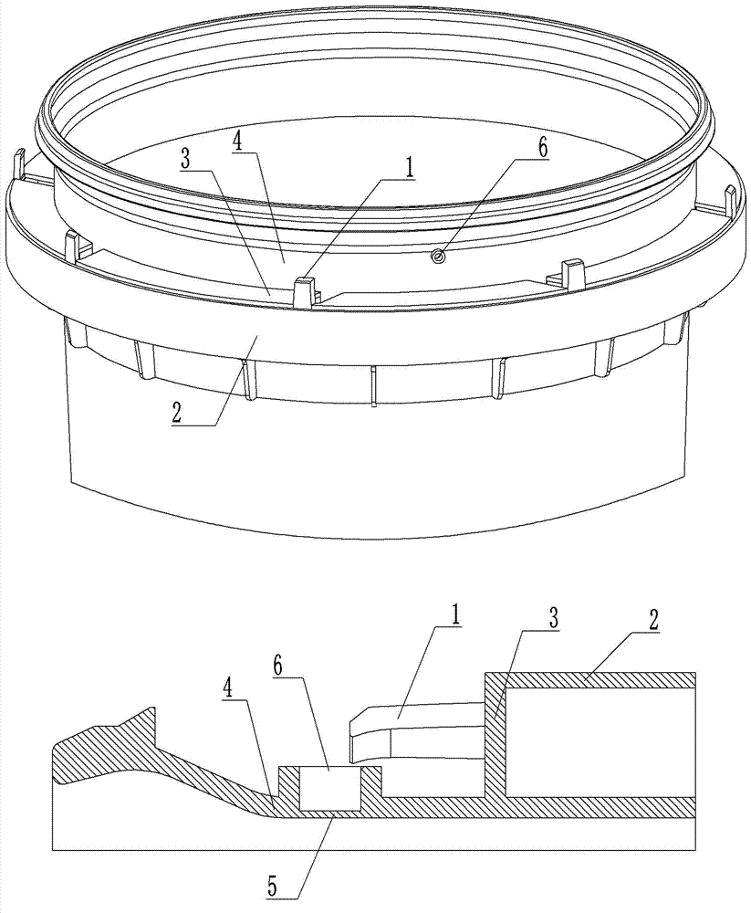
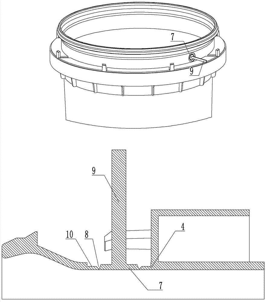
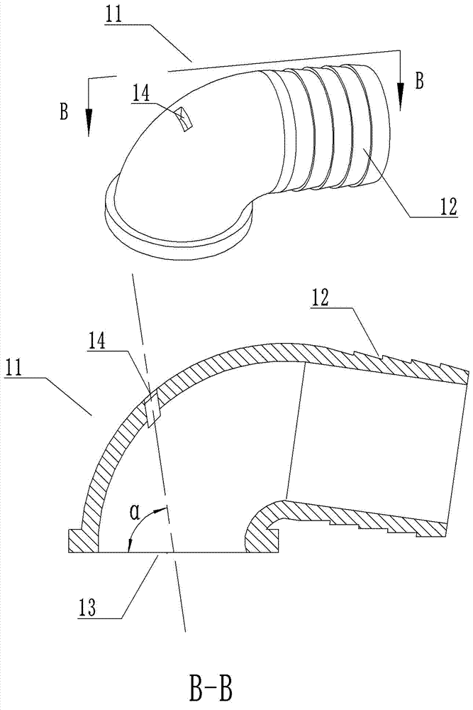
[0103] Embodiment 1, the self-flowing injection molding barrel is composed of a tube side-guided pull-belt diaphragm barrel body assembly with a pull-belt diaphragm as the sealing element, and the barrel cover is fastened, including a card tube side-guided pull-belt diaphragm barrel body, a soft conduit, The puncture needle, the side-guided pulling diaphragm barrel of the card tube is mainly composed of the carding claw, the pulling diaphragm, the venting blind hole, and the guide belt curved catheter. Its form is as follows: figure 1 As shown, the clamping claw 1 is a clamping device evenly arranged at the junction of the barrel body side skirt 2 and the side skirt step 3, and the barrel mouth side wall 4 is provided with a ventilating blind hole 6 with a sealing film 5, and the sealing film The thickness is set to 0.1-0.5mm; if figure 2 As shown, the pull belt diaphragm is arranged on the side wall of the barrel mouth and is connected with a pull belt. The diaphragm 7 is a ...

Embodiment 2

[0105] Embodiment 2, the self-flowing injection molding barrel is composed of a side-guided perforated diaphragm barrel body assembly with a perforated diaphragm as the sealing element and a barrel cover, including a side-guided perforated diaphragm barrel body, a flexible catheter, and a puncture needle. The body of the card tube side-guided perforated diaphragm barrel is mainly composed of a card tube claw, a ventilating blind hole, a perforated diaphragm, a guide belt type curved catheter, a pull ring type pull belt, and a pull belt buckle. Its form is as follows: figure 1 As shown, the clamping claw 1 is a clamping device evenly arranged at the junction of the barrel body side skirt 2 and the side skirt step 3, and the barrel mouth side wall 4 is provided with a ventilating blind hole 6 with a sealing film 5, and the sealing film The thickness is set to 0.1-0.5mm; the perforated diaphragm is a diaphragm with a tear-off hole set on the side wall of the barrel mouth, such as ...

Embodiment 3

[0107] Embodiment 3, the self-flowing injection molding barrel is composed of a side-guided hinged diaphragm barrel body assembly with a hinged diaphragm as the sealing element and a barrel cover, including a side-guided hinged diaphragm barrel body, a flexible catheter, and a puncture needle. The side-guided hinged diaphragm barrel of the card tube is mainly composed of the card tube claw, the blind hole for ventilation, the hinge diaphragm, the guide rod type curved pipe, and the ejector rod. Its form is as follows: figure 1 As shown, the clamping claw 1 is a clamping device evenly arranged at the junction of the barrel body side skirt 2 and the side skirt step 3, and the barrel mouth side wall 4 is provided with a ventilating blind hole 6 with a sealing film 5, and the sealing film The thickness of the barrel is set to 0.1-0.5mm; the hinge diaphragm is a diaphragm with a hinge body and a baffle set on the side wall of the barrel mouth, such as Figure 15 As shown, the diaph...


PUM

PropertyMeasurementUnit
Thicknessaaaaaaaaaa
Wall thicknessaaaaaaaaaa
Thicknessaaaaaaaaaa

Abstract

The invention discloses a self-flow injection method and a self-flow injection molding barrel thereof. A transition diversion tube with a guide tube nozzle is connected to a barrel body or a barrel cover, a sealing element is arranged in the transition diversion tube, a liquid outlet is formed at the transition diversion tube after the sealing element is opened, a breathable blind hole is formed in a position which is opposite to the transition diversion tube, and when oil is injected, the horizontal injection molding barrel is rotated, so that the liquid outlet is controllably switched between a liquid-free cavity and a liquid cavity in the barrel, and a valve device of an existing self-flow valve controlled injection molding barrel is replaced. Thus, the number of parts is reduced, the structure is simple, the assembly is simple and convenient, the manufacturing process is simple, and closing and filling of an automatic line can be implemented, so that the purpose of reducing the cost of unit products is achieved, the auxiliary filling technique is preferably popularized and applied, and the problems of manpower consumption, effort consumption, time consumption, serious waste, environmental pollution and the like because a large quantity of traditional injection molding barrels are used at present are solved.

Description

technical field [0001] The invention belongs to the field of barrel packaging, and in particular relates to a self-flow filling method and a self-flow injection molding barrel. Background technique [0002] In the field of barrel packaging, injection-molded barrels used to pack 10-20 liters of lubricating oil or antifreeze are generally called injection-molded barrels. The valve-controlled filling method and its self-flowing valve-controlled injection barrel mainly solve many shortcomings of traditional injection barrels when filling oil. The technical solution is to symmetrically set liquid outlet holes and The air intake hole of the waterproof and breathable membrane uses a valve and a flexible conduit to assist in diversion. The filling steps are: 1. Connect the valve and the flexible conduit to the liquid outlet; 2. Close the valve; 3. Place the injection barrel horizontally so that the liquid outlet faces Next; 4. Insert the soft conduit into the filling port; 5. Open ...

Claims


Application Information

Patent Timeline
IPC IPC(8): B65D25/38B67D7/02B67D7/04
CPCB65D25/38B67D7/0294B67D7/04
Inventor 杨鹏翔杨海天杨西娟
Owner 杨鹏翔
Why Eureka
Try Eureka