Automatic clutch driving mechanism, engine and motorcycle

A driving mechanism, automatic clutch technology, applied in the direction of mechanical drive clutches, clutches, mechanical equipment, etc., can solve the problems of large driving stroke of the clutch control rocker arm, low driving efficiency of the clutch cam disc, and complicated force conditions, and improve the driving force. force, avoid large driving resistance, and improve the effect of smoothness

Pending Publication Date: 2017-11-07
CHONGQING LONCIN ENGINE +1
View PDF5 Cites 2 Cited by
  • Summary
  • Abstract
  • Description
  • Claims
  • Application Information

AI Technical Summary

Problems solved by technology

[0002] The automatic clutch drive mechanism is an important mechanism for engine gear shifting. The clutch is controlled by the clutch control rocker arm installed on the shift shaft. When the driver drives the shift shaft to rotate, the clutch control rocker arm rotates before the transmission drum, thereby realizing automatic Clutch shifting is convenient for the driver to shift gears. Generally, the clutch control rocker arm is rotated and provided with rollers. The rollers are used to cooperate with the profiled line rolling drive of the clutch cam disc on the clutch to realize the reciprocating swing of the clutch cam disc along the circumferential direction. And then realize the separation and combination of the clutch; while the profiles set on the clutch cam disc in the prior art are two straight lines distributed along the radial direction, but the rollers revolve and rotate at the same time when the clutch control rocker arm rotates, while the rollers At the same time, it is subject to the driving force of the clutch control rocker arm and the resistance of the shape line, resulting in complex force conditions, large driving resistance, and prone to drive jamming, and poor ride comfort; at the same time, the drive stroke of the clutch control rocker arm is relatively large, making the The drive efficiency of clutch cam disc oscillation is low

Method used


Image

  • Automatic clutch driving mechanism, engine and motorcycle
  • Automatic clutch driving mechanism, engine and motorcycle
  • Automatic clutch driving mechanism, engine and motorcycle

Examples


Embodiment Construction

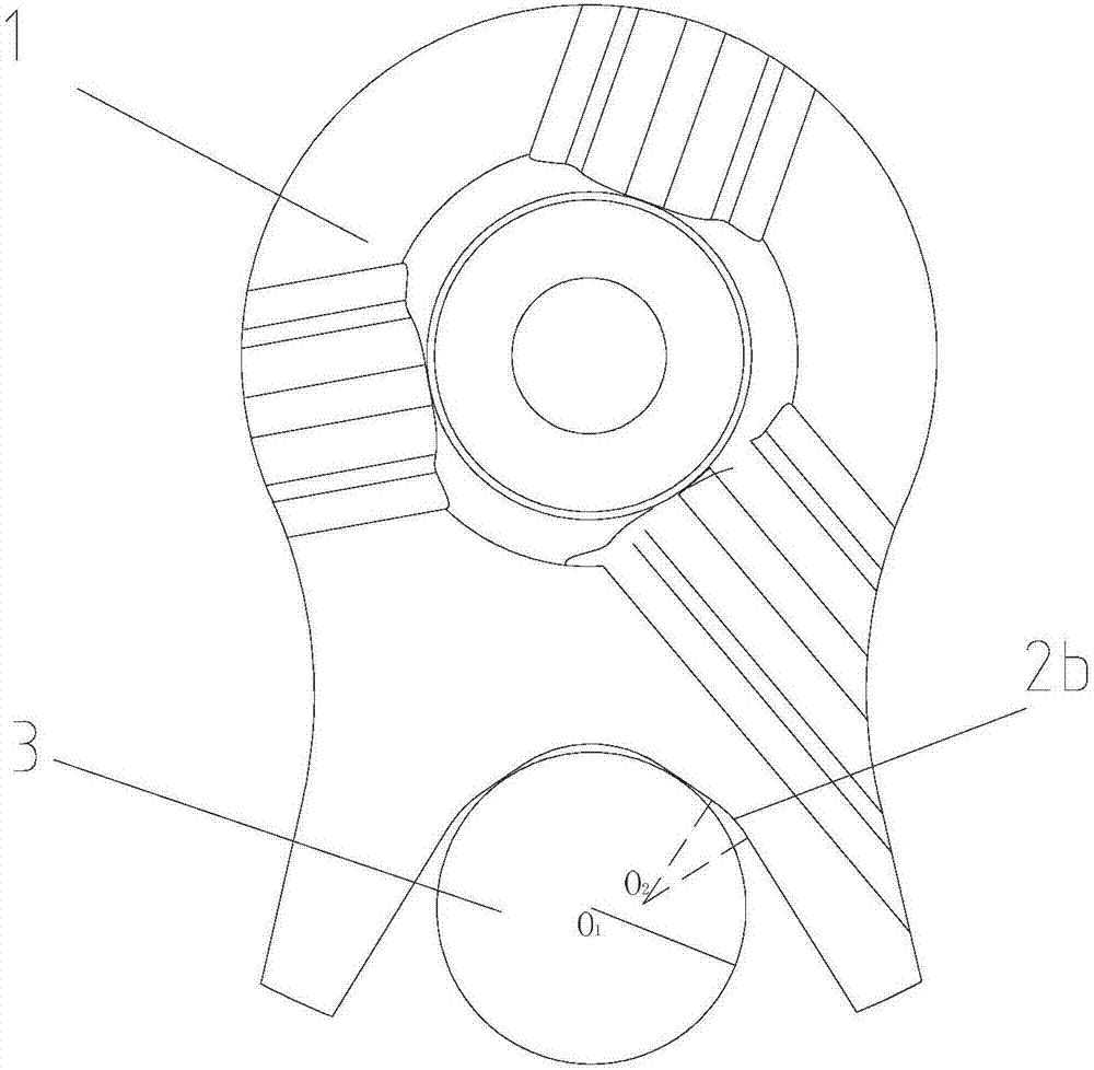
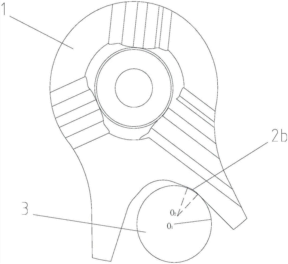
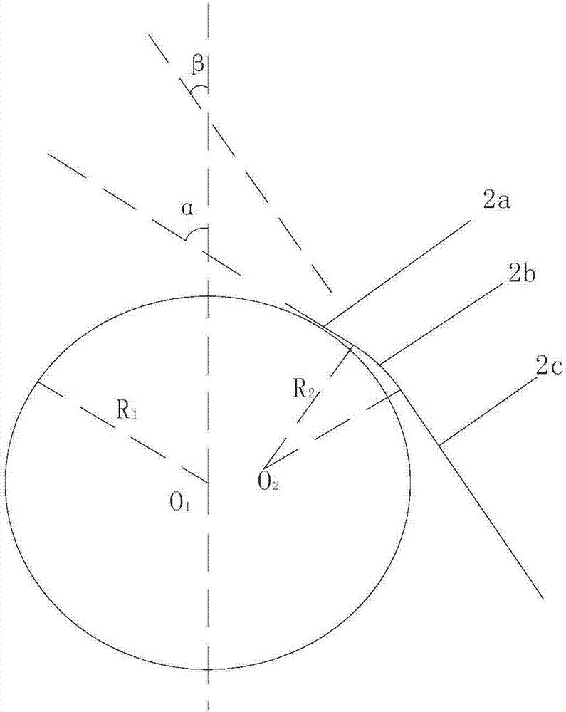
[0021] figure 1 It is a structural schematic diagram of the present invention, figure 2 It is a structural schematic diagram after the rotation of the clutch cam disc in the present invention, image 3 It is a structural schematic diagram of the medium-sized wire of the present invention, Figure 4 It is a structural schematic diagram of the engine in the present invention. As shown in the figure, the automatic clutch drive mechanism in this embodiment includes a clutch cam plate and a clutch control rocker arm, the clutch cam plate is provided with an opening groove, and the clutch control rocker arm The clutch cam plate is driven to rotate through the open slot to complete the clutch; the curve formed by the cross section of the open slot on its side wall is the driving profile, which is symmetrical as a whole and gradually becomes larger from the inside to the outside , the single side of the driving line includes the first straight line and the curved line from inside t...


PUM


Abstract

The invention discloses an automatic clutch driving mechanism, an engine and a motorcycle. The automatic clutch driving mechanism comprises a clutch cam disc and a clutch operating rocker arm, wherein an open groove is formed in the clutch cam disc; the clutch operating rocker arm drives the clutch cam disc to rotate through the open groove, and separation and reunion of a clutch are achieved; a curve formed by the cross section of the open groove on the side wall is a driving line; the driving line is integrally symmetrical and is gradually increased from inside to outside; and the single side edge of the driving line sequentially comprises a first linear section and a curve section from inside to outside. According to the automatic clutch driving mechanism, driving resistance of the automatic clutch driving mechanism is prevented from being relatively large, resistance suffered by the clutch operating rocker arm is improved through the curve section, blocking is avoided, smoothness of automatic clutch driving is improved, and comfort during gear shifting operation is guaranteed.

Description

technical field [0001] The invention relates to a shift auxiliary mechanism, an engine and a motorcycle, in particular to an automatic clutch drive mechanism, an engine and a motorcycle. Background technique [0002] The automatic clutch drive mechanism is an important mechanism for engine gear shifting. The clutch is controlled by the clutch control rocker arm installed on the shift shaft. When the driver drives the shift shaft to rotate, the clutch control rocker arm rotates before the transmission drum, thereby realizing automatic Clutch shifting is convenient for the driver to shift gears. Generally, the clutch control rocker arm is rotated and provided with rollers. The rollers are used to cooperate with the profiled line rolling drive of the clutch cam disc on the clutch to realize the reciprocating swing of the clutch cam disc along the circumferential direction. And then realize the separation and combination of the clutch; while the profiles set on the clutch cam di...

Claims


Application Information

Patent Timeline
Patent Type & Authority Applications(China)
IPC IPC(8): F16D23/14F16H63/30
CPCF16D23/14F16H63/30F16D2023/141
Inventor 杜龙何涛刘建文杨正靖陈艺方程仕杰
Owner CHONGQING LONCIN ENGINE
Why Eureka
Try Eureka